2-3
2 Nomenclature and Installation
CJ-series PROFIBUS Master Unit Operation Manual for NJ-series CPU Unit (W509)
2-1 Unit Components
2
2-1-3 Switch Settings
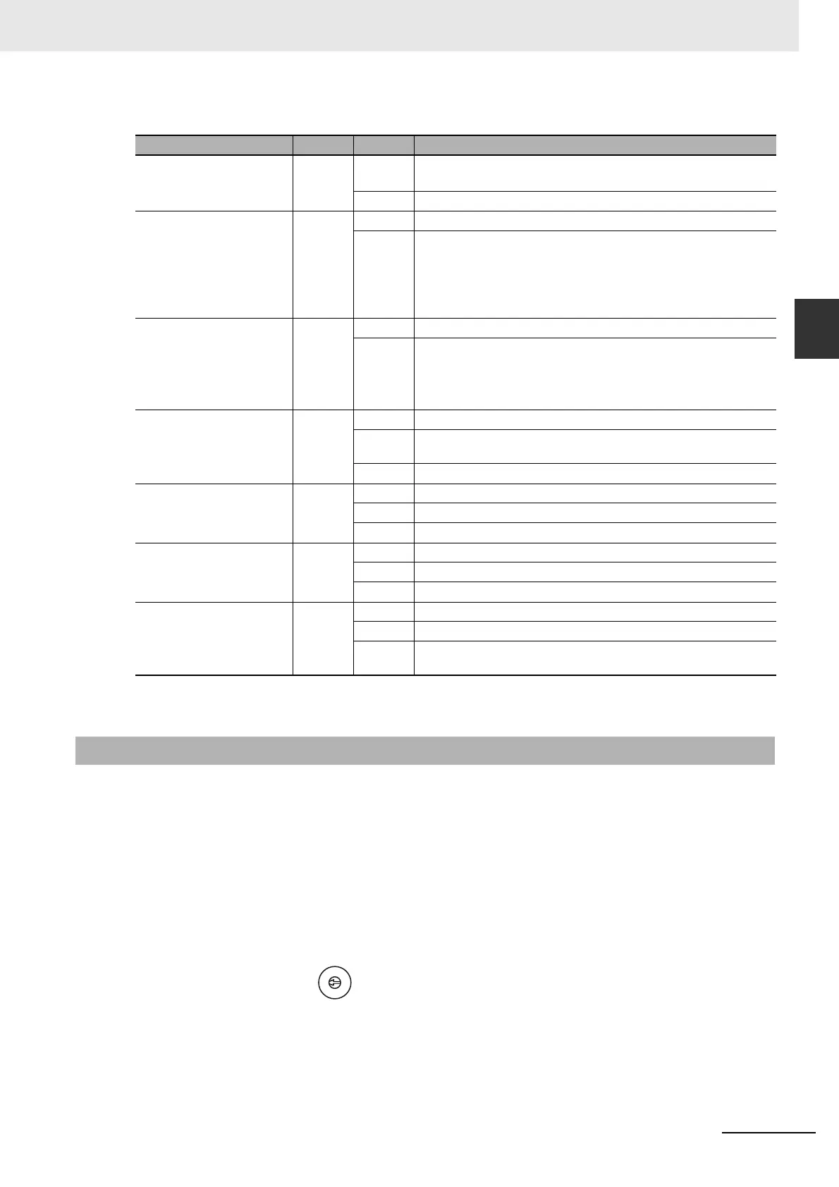
Indicator Specifications
Note Unless otherwise specified, the frequency of a flashing indicator is 1 Hz (50% duty cycle).
Setting the Unit Number
The unit number is used to identify individual CPU Bus Units when more than one CPU Bus Unit is
mounted to the same CPU. The unit number must be unique for each CPU Bus Unit. Selecting a
non-unique number for a CPU Bus Unit will prevent the NJ-series controller unit from starting cor-
rectly.
1
Turn OFF the power supply before setting the Unit number.
2
Set the switch to the new Unit number. Use a small screwdriver to make the setting, taking care
not to damage the rotary switch. The unit number is factory-set to 0.
Indicator Color Status Meaning
RUN Green Not lit • Startup test failed, Unit not operational.
• Operation stopped, due to a fatal error.
Lit Initialization successful, Unit is in normal operation.
ERC
(PROFIBUS Master Unit
Error)
Red Not lit Unit is in normal operation.
Lit • One of the following errors occurred:
• Startup error.
• Non-volatile memory error (checksum failed, write-verify failed).
• Invalid PROFIBUS parameter configuration setting.
• Fatal error in program execution.
ERH
(CPU Error)
Red Not lit CPU in normal operation.
Lit One of the following errors occurred:
• CPU Bus error.
• Cyclic Refresh Monitor Time-out.
• Routing table error.
PRM
(Parameter database)
Green Not lit PROFIBUS Parameter configuration is not available or incorrect.
Flashing PROFIBUS Parameter configuration is being transferred to the Unit
and is not yet available.
Lit PROFIBUS Parameter configuration is correct, and operational.
BST
(Bus status)
Green Not lit The PROFIBUS Master Unit is in OFFLINE or STOP mode.
Flashing The PROFIBUS Master Unit is in CLEAR mode.
Lit The PROFIBUS Master Unit is in OPERATE mode.
COMM
(I/O Data communication)
Green Not lit No PROFIBUS data exchange with any of the allocated slaves.
Flashing Fatal error occurred (ERC indicator is ON). Unit initialization failed.
Lit PROFIBUS data exchange ongoing with at least one allocated slave.
BF
(Bus Fail)
Red Not lit No PROFIBUS communication errors occurred.
Flashing At least one allocated slave is not in data exchange with the Unit.
Lit An error occurred in the PROFIBUS interface of the Unit (see section
7-2 Troubleshooting with the PROFIBUS Master Unit Indicators).
2-1-3 Switch Settings
NO.
UNIT
0
1
2
3
4
5
6
7
8
9
A
B
C
D
E
F
Setting range:
0 to F (Hexadecimal)

 Loading...


