EasyManuals Logo

Omron CP1E - INTRODUCTION User Manual

Omron CP1E - INTRODUCTION
182 pages
To Next Page IconTo Next Page
To Previous Page IconTo Previous Page
Page #23 background imageLoading...
Page #23 background image
SECTION 2
Designing Systems
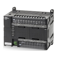
This section explains how to construct a CP1L (14-point I/O unit
with AC power supply) system based on the shutter control system
as an example.
All subsequent sections are written based on the sample program
used in this section.
2-1 Organization of this Manual .................................................. 22
2-2 About the Shutter Control System ........................................ 24
2-2-1 Operation........................................................................ 24
2-2-2 System Components ...................................................... 25
2-3 I/O Allocation for the Shutter Control System ....................... 26
2-4 Example Ladder Program ..................................................... 28

Table of Contents

Questions and Answers:

Question and Answer IconNeed help?

Do you have a question about the Omron CP1E - INTRODUCTION and is the answer not in the manual?

Omron CP1E - INTRODUCTION Specifications

General IconGeneral
SeriesCP1E
ManufacturerOmron
Input Voltage100 to 240 VAC or 24 VDC (depending on model)
I/O Points10 to 60 points
Number of Inputs6 to 36 points
Number of Outputs4 to 24 points
Communication PortsUSB, RS-232C
Programming LanguageLadder Diagram (LD)
Power Supply100-240V AC or 24V DC
Storage Temperature-25°C to 65°C
Vibration Resistance10 to 57 Hz, 0.075mm amplitude
Shock Resistance147 m/s², 3 times each in X, Y, Z directions
WeightVaries by model
TypeProgrammable Logic Controller (PLC)

Related product manuals