A
Appendix
A-4 CP1L Programming Examples
168 SYSMAC CP1L/CP1E Introduction Manual
A-4-9 Exchanging Data between CP1Ls
■Functions Used
●Simple PLC Link
By using RS-422A/485 option boards, up to 10CH of data per CPU unit can be shared
by as many as 9 CP1L/CP1H/CJ1M units, without the aid of a program.
■Operation Overview
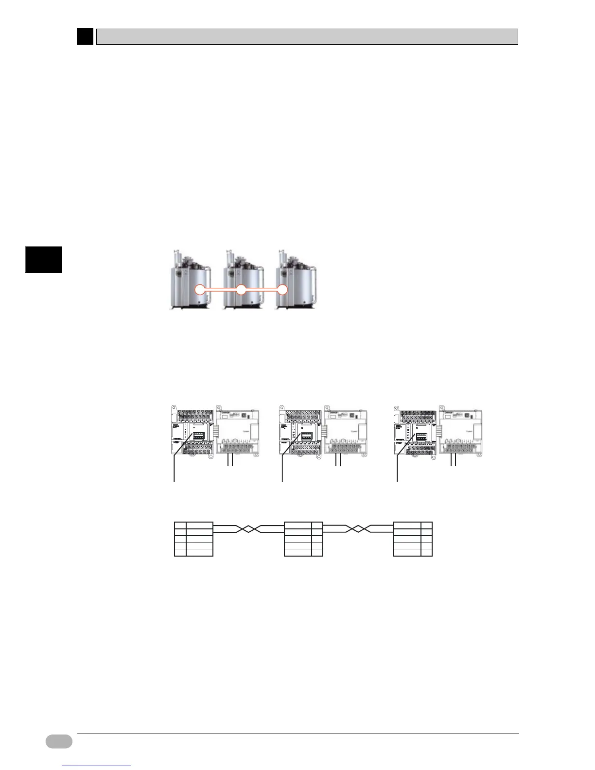
Current temperature information is exchanged by boilers.
This setup may be used to adjust boiler temperatures according to the other boiler
conditions, or to monitor the boilers from a single location.
■System Configuration
●Wiring Example
Boiler A Boiler B Boiler C
1CH,2CH
Temperature sensor unit
CP1W-TS101
2 Pt100 sensor inputs
(E52-P10AE) (E52-P10AE) (E52-P10AE)
CP1W-CIF11/12
(RS422/485 option board)
1CH,2CH
2 Pt100 sensor inputs
CP1W-CIF11/12
(RS422/485 option board)
1CH,2CH
2 Pt100 sensor inputs
CP1W-CIF11/12
(RS422/485 option board)
1
CP1W-CIF11/12
2
4
5
RDA-
3
RDB+
SDA-
SDB+
FG
Simple PLC link
1
CP1W-CIF11/12
2
4
5
RDA-
3
RDB+
SDA-
SDB+
FG
1
CP1W-CIF11/12
2
4
5
RDA-
3
RDB+
SDA-
SDB+
FG
Boiler A: CP1L (Master) Boiler B: CP1L (Slave No.0)
Boiler C: CP1L (Slave No.1)
Temperature sensor unit
CP1W-TS101
Temperature sensor unit
CP1W-TS101
RDA- RDB+ SDA- SDB+ FG
COMM
RDA- RDB+ SDA- SDB+ FG
COMM
RDA- RDB+ SDA- SDB+ FG
COMM

 Loading...


