2-3 I/O Allocation for the Shutter Control System
2
2
SYSMAC CP1L/CP1E Introduction Manual 27
Designing Systems
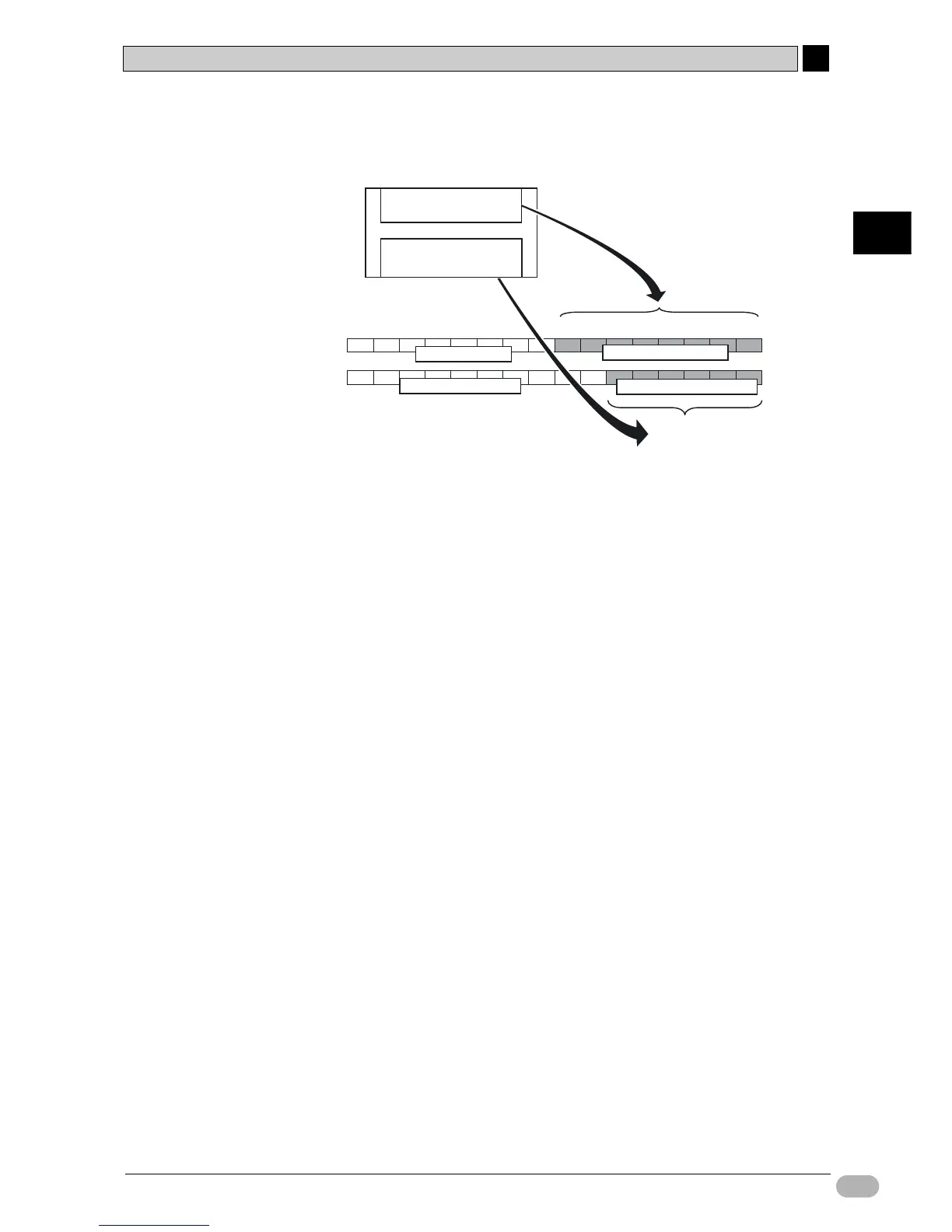
●I/O Allocation on CP1L with 14-point I/O
On 14-point I/O units, 8 input relays, from 0.00 to 0.07 (bits 00 to 07 on 0CH),
are allocated to the input terminal block.
Also, 6 output relays, from 100.00 to 100.05 (bits 00 to 05 on 100CH), are
allocated to the output terminal block.
Unused upper bits on the input channel (bits 08 to 15) cannot be used as a work
area. Unused upper bits on the output channel (bits 06 to 15) , however, can be
used.
Output Area
Input Area
8 inputs
6 outputs
0 CH (0.00~0.07)
100 CH (100.00~100.05)
15 14 13 12 11 10 09 08 07 06 05 04 03 02 01 00
0 CH
100 CH
Input area : 8 inputs
Output area : 6 outputs
Used as work area
Allocate
Allocate
Not available

 Loading...


