3
32 SYSMAC CP1L/CP1E Introduction Manual
3-1 Installation Notes
3
Mounting and Wiring
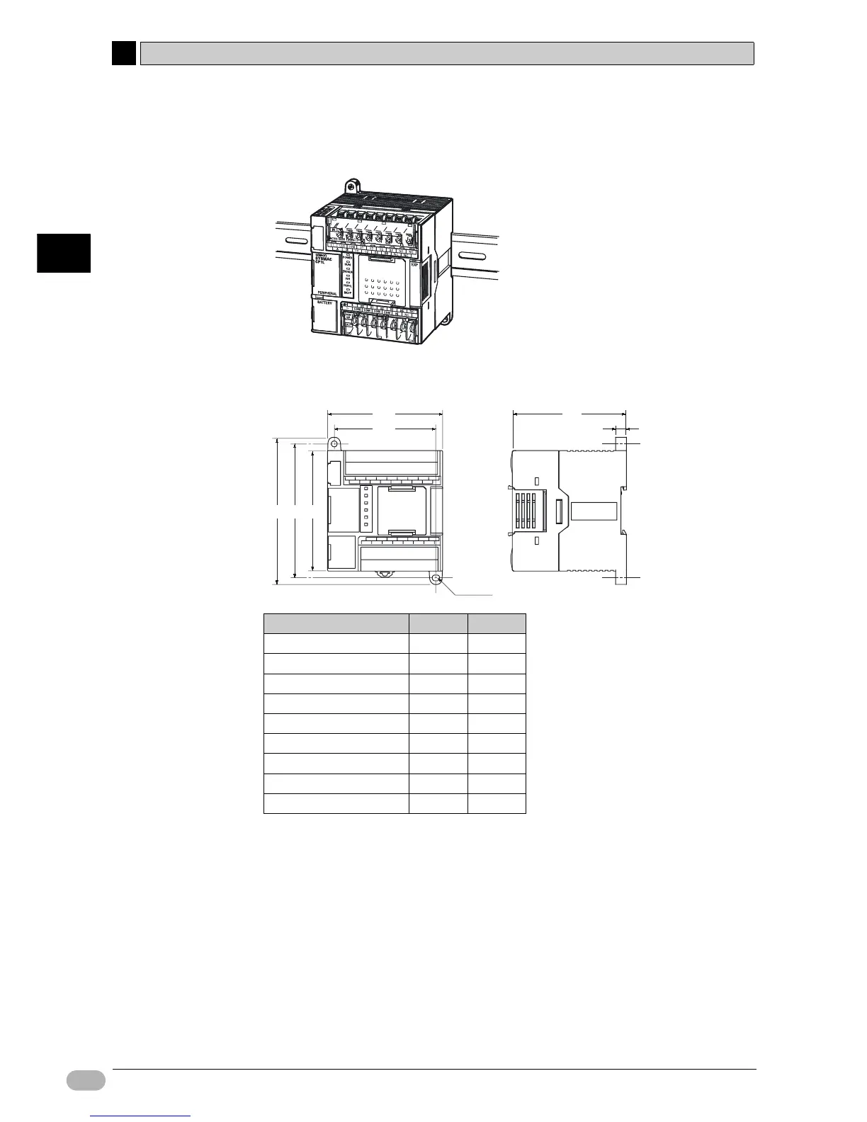
●Mounting
For heat dissipation, mount CP1L in the orientation shown below.
■External Dimensions
■DIN Track
Secure the DIN track onto the control panel, using at least 3 screws.
• Use M4 screws at intervals of 210mm (6 holes) or less. Screw torque is
1.2N
·m.
For details on installing CP1L, refer to SECTION 3 Installation and Wiring of CP
Series CP1L CPU Unit User’s Manual (W462) or SECTION 5 Installation and
Wiring of CP Series CP1E CPU Unit Hardware User's Manual (W479).
Model W1 W2
CP1L-L10D- 66 56
CP1L-L14D- 86 76
CP1L-L20D- 86 76
CP1E-20D- 86 76
CP1L-M30D- 130 120
CP1E-30D- 130 120
CP1L-M40D- 150 140
CP1E-40D- 150 140
CP1L-M60D- 195 185
W1
W2
110
100 90
4-φ4.5
85
8

 Loading...


