90
Pulse I/O Board Section 2-2
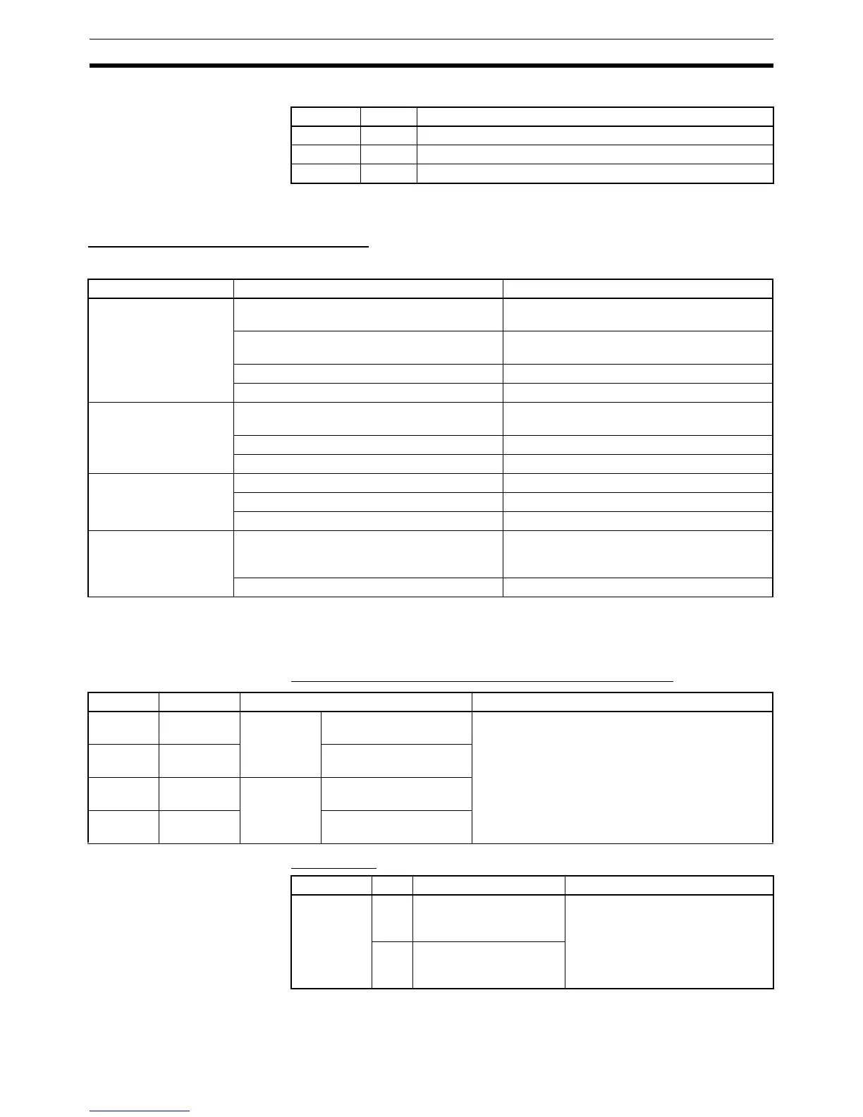
Pulse Input Indicators
2-2-6 Specifications
High-speed Counter Specifications
Instructions
Relevant Flags and
Control Bits for Pulse
Inputs
Bits for Slot 2 of Inner Board when Using Pulse I/O Board
SR Area Bits
Port 1 Port 2 Function
A1 A2 Lit when the phase-A pulse input is ON at the port.
B1 B2 Lit when the phase-B pulse input is ON at the port.
Z1 Z2 Lit when the phase-Z pulse input is ON at the port.
Instruction Control Meaning
(@)CTBL(63) Range comparison table registration + com-
parison start
Registers range comparison table and starts
comparison.
Target value table registration + comparison
start
Registers target value table and starts com-
parison.
Range comparison table registration Registers range comparison table.
Target value table registration Registers target value table.
(@)INI(61) Comparison start Starts comparison using registered compari-
son table.
Comparison stop Stops comparison.
PV change Changes PV of high-speed counter.
(@)PRV(62) PV read Reads PV of high-speed counter.
Status read Reads status of high-speed counter.
Range comparison result read Reads range comparison result.
(@)INT(89) Masking all interrupts asking all interrupts, such as input interrupts,
interval timer interrupts, and high-speed
counter interrupts.
Clearing interrupt masks Clears masks from interrupts.
Word Bits Name Function
IR 232 00 to 15 Port 1 PV word (rightmost four
digits)
The PV of the high-speed counter for each port of
the Pulse I/O Board is stored as an 8-digit BCD
value after each cycle.
IR 233 00 to 15 PV word (leftmost four
digits)
IR 234 00 to 15 Port 2 PV word (rightmost four
digits)
IR 235 00 to 15 PV word (leftmost four
digits)
Word Bit Name Function
SR 252 01 High-speed Counter 1
Reset Bit (port 1)
Phase Z and software reset
0: Counter not reset on phase Z
1: Counter reset on phase Z
Software reset only
0: Counter not reset
0→1: Counter reset
02 High-speed Counter 2
Reset Bit (port 2)
 Loading...


