69
High-speed Counter Board Section 2-1
2-1-7 High-speed Counters 1 to 4
The High-speed Counter Board counts pulse signals entering through ports 1
to 4 from rotary encoders and outputs internal/external output bit patterns
according to the number of pulses counted. The four ports can be used inde-
pendently. An outline of the processing performed by high-speed counters 1
to 4 is provided below.
Overview of Process
Input Signals and Input
Modes
High-speed counters 1 to 4 can be set to different Input Modes in response to
the type of signal input.
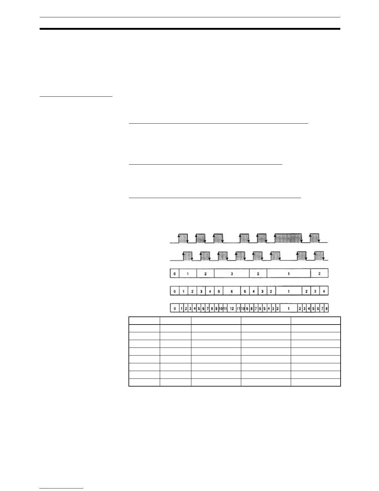
Differential Phase Mode (Counting Speed: 25 kHz or 250 kHz)
Two phase signals (phase A and phase B) with phase difference multiples of
1x, 2x, or 4x are used together with a phase-Z signal for inputs. The count is
incremented or decremented according to differences in the two phase sig-
nals.
Up/Down Mode (Counting Speed: 50 kHz or 500 kHz)
Phase A is the incrementing pulse and phase B is the decrementing pulse.
The counter increments or decrements according to the pulse that is
detected.
Pulse/Direction Mode (Counting Speed: 50 kHz or 500 kHz)
Phase A is the pulse signal and phase B is the direction signal. The counter
increments when the phase-B signal is ON and decrements when it is OFF.
Phase A Phase B 1x 2x 4x
↑ L Increment Increment Increment
H ↑ --- --- Increment
↓ H --- Increment Increment
L ↓ --- --- Increment
L ↑ --- --- Decrement
↑ H --- Decrement Decrement
H ↓ --- --- Decrement
↓ L Decrement Decrement Decrement
Phase A
Phase B
Differential Phase Mode
1x
2x
4x
 Loading...


