222
Ladder Diagram Instructions Section 5-8
5-8 Ladder Diagram Instructions
Ladder diagram instructions include ladder instructions and logic block
instructions and correspond to the conditions on the ladder diagram. Logic
block instructions are used to relate more complex parts.
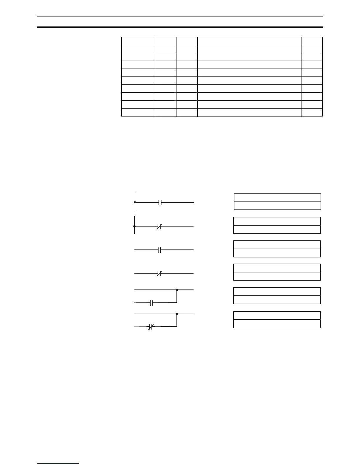
5-8-1 LOAD, LOAD NOT, AND, AND NOT, OR, and OR NOT
Limitations There is no limit to the number of any of these instructions, or restrictions in
the order in which they must be used, as long as the memory capacity of the
PC is not exceeded.
Description These six basic instructions correspond to the conditions on a ladder diagram.
As described in SECTION 4 Ladder-diagram Programming, the status of the
bits assigned to each instruction determines the execution conditions for all
other instructions. Each of these instructions and each bit address can be
used as many times as required. Each can be used in as many of these
instructions as required.
The status of the bit operand (B) assigned to LD or LD NOT determines the
first execution condition. AND takes the logical AND between the execution
condition and the status of its bit operand; AND NOT, the logical AND
XFRB (@) –– 4 TRANSFER BITS 279
XNRW (@) 37 4 EXCLUSIVE NOR 375
XORW (@) 36 4 EXCLUSIVE OR 374
ZCP –– 4 AREA RANGE COMPARE 289
ZCPL –– 4 DOUBLE AREA RANGE COMPARE 290
+F (@) –– 4 FLOATING-POINT ADD 355
–F (@) –– 4 FLOATING-POINT SUBTRACT 357
*F (@) –– 4 FLOATING-POINT MULTIPLY 358
/F (@) –– 4 FLOATING-POINT DIVIDE 359
Mnemonic Code Words Name Page
B: Bit
IR, SR, AR, HR, TIM/CNT, LR, TR
Ladder Symbols Operand Data Areas
LOAD LD
B
B: Bit
IR, SR, AR, HR, TIM/CNT, LR
LOAD NOT LD NOT
B
B: Bit
IR, SR, AR, HR, TIM/CNT, LR
AND AND
B
B: Bit
IR, SR, AR, HR, TIM/CNT, LR
AND NOT AND NOT
B
B: Bit
IR, SR, AR, HR, TIM/CNT, LR
OR OR
B
B: Bit
IR, SR, AR, HR, TIM/CNT, LR
OR NOT OR NOT
B
 Loading...


