137
Analog I/O Board Section 2-5
Related PC Setup Settings None
2-5 Analog I/O Board
2-5-1 Model
2-5-2 Function
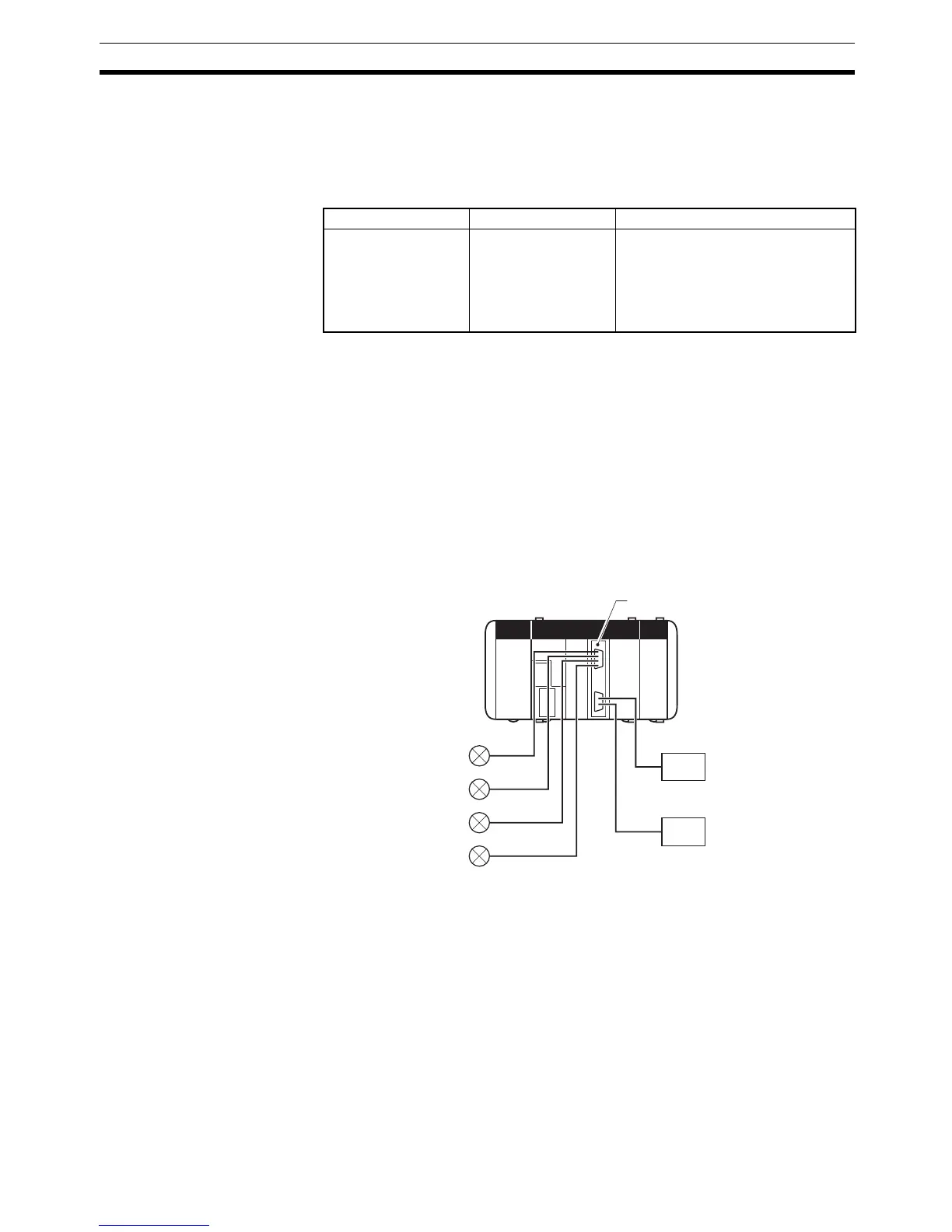
The Analog I/O Board is an Inner Board featuring four analog inputs and two
analog outputs.
The signal ranges that can be used for each of the four analog input points are
–10 to +10 V, 0 to 5 V, and 0 to 20 mA. A separate range is set for each point.
The settings in DM 6611 determine the signal ranges.
The signal ranges that can be used for each of the two analog output points
are –10 to +10 V and 0 to 20 mA. A separate signal range can be selected for
each point. The settings in DM 6611 determine the signal range.
2-5-3 System Configuration
Name Model Specifications
Analog I/O Board CQM1H-MAB42 4 analog inputs (–10 to +10 V; 0 to 5
V; 0 to 20 mA; separate signal range
for each point)
2 analog outputs (–10 to +10 V; 0 to
20 mA; separate signal range for
each point)
Analog I/O Board
Four analo
 Loading...


