505
Troubleshooting Flowcharts Section 8-7
3. 2 to F Hex: You can disable the log so that no records are stored.
The default setting is the first method. Refer to Error Log Settings on page 17
for details on the PC Setup for the error log.
Note 1. If a Memory Cassette with a clock (RTC) is not used, the date and time of
error occurrence will be “0000.”
2. Error will be recorded in the error log even if DM 6144 to DM 6655 are
write-protected by turning ON pin 1 on the DIP switch on the front side of
the CPU Unit.
Clearing the Error Log To clear the entire error log, turn ON SR 25214 from a Programming Device
or using an instruction. (After the error log has been cleared, SR 25214 will
turn OFF automatically.)
8-7 Troubleshooting Flowcharts
Use the following flowcharts to troubleshoot errors that occur during opera-
tion.
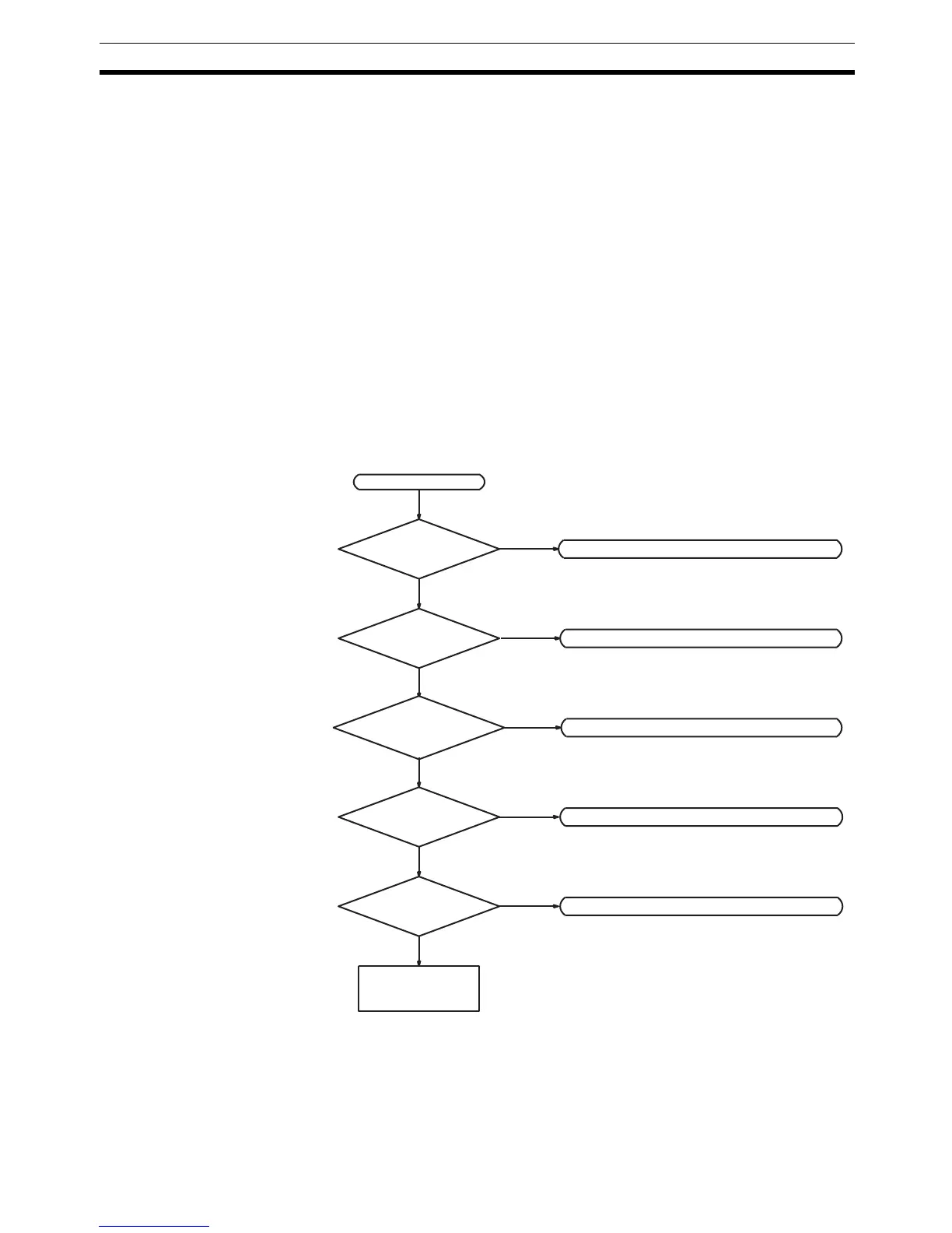
Main Check
Note Always turn OFF the power to the PC before replacing Units, batteries, wiring,
or cables.
Check for non-fatal errors.
Error
Replace the CPU
Unit.
Power indicator lit?
RUN indicator lit?
ERR/ALM indicator
flashing?
Is I/O sequence
normal?
Check for fatal errors.
Check I/O.
Check operating environment.
Lit
Check power supply.
Not lit
Not normal
Not lit
Not normal
Flashing
Normal
Normal
Not lit
Lit
Operating
environment
normal?
(See page 506.)
(See page 507.)
(See page 508.)
(See page 509.)
(See page 511.)
 Loading...


