393
Special Instructions Section 5-28
5-28-9 SET PULSES – PULS(65)
Limitations N and N+1 must be in the same data area.
DM 6143 to DM 6655 cannot be used for N.
Description PULS(65) can be used with the functions listed in the following table.
PULS(65) is used to set parameters for pulse outputs that are started later in
the program using SPED(64) or ACC(––). The parameters that can be set are
the number of pulses that will be output in independent mode, the direction of
pulse outputs from ports 1 and 2, and the deceleration point for pulse outputs
controlled by ACC(––) mode 0.
Since PULS(65) has a relatively long execution time, the cycle time can be
reduced by executing the differentiated version (@PULS(65)) of this instruc-
tion only when it is needed.
Note Refer to 1-5 Pulse Output Function for more details.
Port Specifier (P) The port specifier indicates the pulse output location. The parameters set in C
and N will apply to the next SPED(64) or ACC(––) instruction in which the
same port output location is specified.
Note The bit between 00 and 15 that is output as the contact pulse is specified by
the P operand in SPED(64),
Control Data (C) The control data determines the direction of the pulse output to ports 1 and 2
and indicates whether the number of pulses and/or the deceleration point are
specified in N to N+3. This operand should be set to 000 when an output bit is
specified in P (P=@@0).
P: Port specifier
000, 001
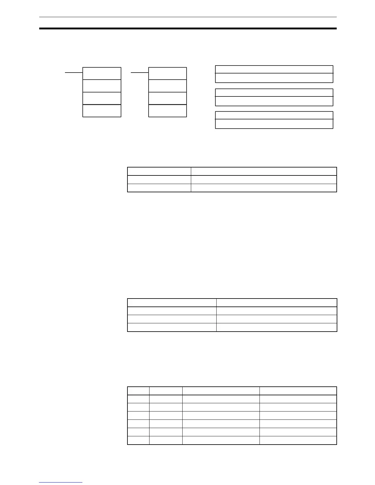
Ladder Symbols Operand Data Areas
@PULS(65)
P
C
N
N: Number of pulses
IR, SR, AR, DM, EM, HR, LR
C: Control data
000 to 005
PULS(65)
P
C
N
Unit/Board Function
Transistor Output Unit Pulse outputs
Pulse I/O Board Pulse outputs 1 and 2
Pulse output location P
Output bits 00 to 15 (See note.) 000
Port 1 001
Port 2 002
C Direction Number of pulses Deceleration point
000 CW Set in N and N+1 Not set.
001 CCW Set in N and N+1 Not set.
002 CW Set in N and N+1 Set in N+2 and N+3
003 CCW Set in N and N+1 Set in N+2 and N+3
004 CW Not set. Not set.
005 CCW Not set. Not set.