140
Analog I/O Board Section 2-5
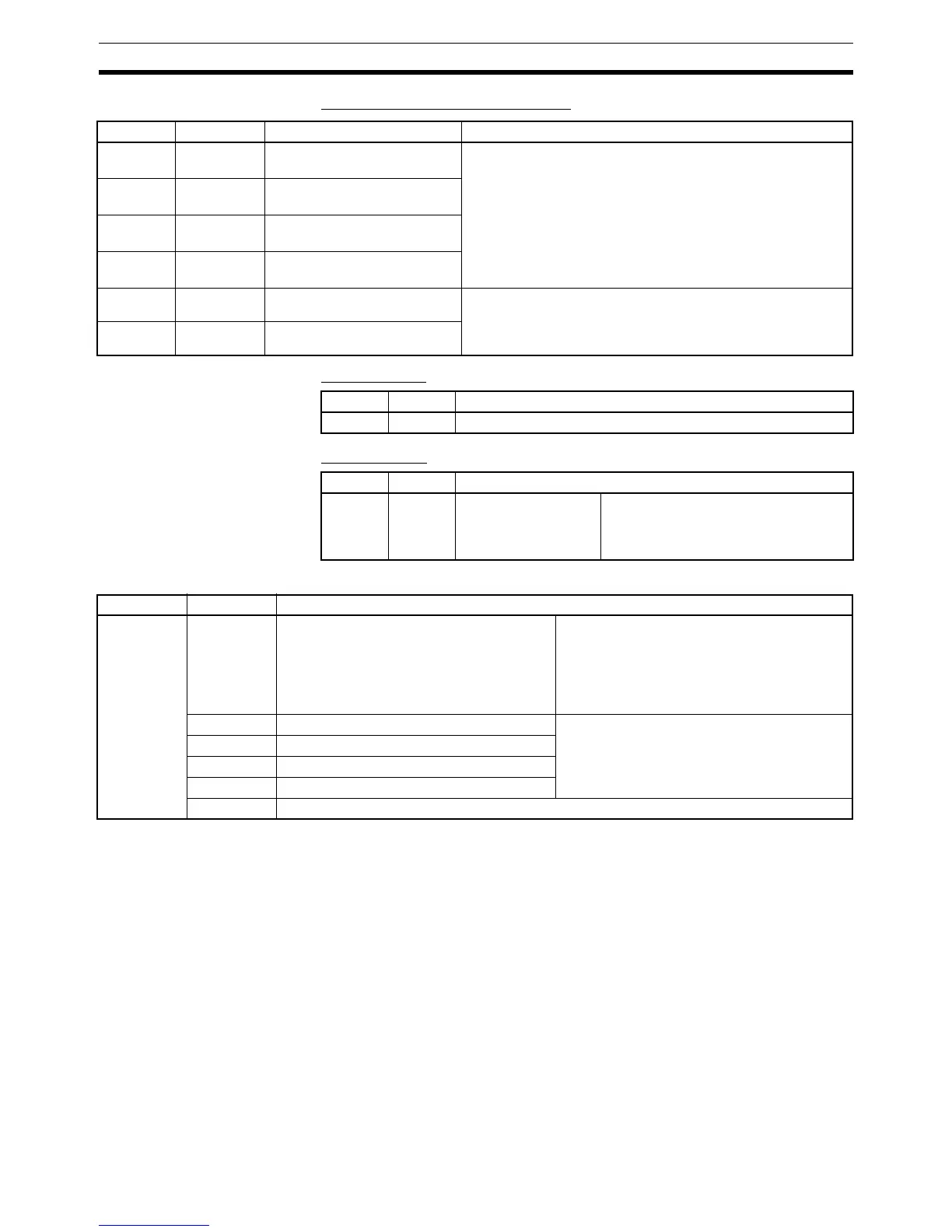
Relevant Bits Bits Used by Inner Board in Slot 2
SR Area Flags
AR Area Flags
Relevant PC Setup Settings
Note The level of the analog output signal is determined by the connected terminal,
and there is no PC Setup setting. These settings are reflected in status at
power ON.
Word Bits Name Function
IR 232 00 to 15 Analog input 1 converted
value
The converted value from each input from the Analog I/O
Board is stored as a 4-digit Hex each cycle.
–10 to +10 V: F800 to 07FFF Hex
0 to 10 V: 0000 to 0FFF Hex
0 to 5 V/0 to 20 mA: 0000 to 0FFF Hex
IR 233 00 to 15 Analog input 2 converted
value
IR 234 00 to 15 Analog input 3 converted
value
IR 235 00 to 15 Analog input 4 converted
value
IR 236 00 to 15 Analog output 1 setting The setting of each output from the Analog I/O Board is stored
as a 4-digit Hex. (Read each cycle.)
–10 to +10 V: F800 to 07FF Hex
0 to 20 mA: 0000 to 07FF Hex
IR 237 00 to 15 Analog output 2 setting
Word Bit Function
SR 254 15 Inner Board Error Flag
Word Bits Function
AR 04 08 to 15 Error codes for Inner
Board in slot 2
00 Hex: Normal
01 or 02 Hex: Hardware error
03 Hex: PC Setup error
04 Hex: A/D or D/A conversion error
Word Bits Function
DM 6611 00 to 07 00, 01: Analog input 1 input signal range
02, 03: Analog input 2 input signal range
04, 05: Analog input 3 input signal range
06, 07: Analog input 4 input signal range
00: –10 to +10 V
01: 0 to 10 V
10: 0 to 5 V/0 to 20 mA
11: Not used.
(0 to 20 mA are distinguished by the con-
nected terminal.)
08 Analog input 1 usage selection Specifies use or non-use of A/D conversion for
each port.
0: Use input (conversion)
1: Do not use input (no conversion)
09 Analog input 2 usage selection
10 Analog input 3 usage selection
11 Analog input 4 usage selection
12 to 15 Not used. (Fixed at 0.)
 Loading...


