425
Advanced I/O Instructions Section 5-31
The value of C indicates the number of digits of source data and the logic for
the Input and Output Units, as shown in the following table.
If there are 8 digits of source data, they are placed in S and S+1, with the
most significant digits placed in S+1. If there are 4 digits of source data, they
are placed in S.
7SEG(88) displays the 4 or 8-digit data in 12 cycles, and then starts over and
continues displaying the data.
Refer to page 424 for more information on 7SEG(88) and its applications.
Flags ER: S and S+1 are not in the same data area. (When set to display 8-digit
data.)
Indirectly addressed EM/DM word is non-existent.
(Content of *EM/*DM word is not BCD, or the EM/DM area boundary
has been exceeded.)
There is an error in operand settings.
SR 25409: ON while 7SEG(88) is being executed.
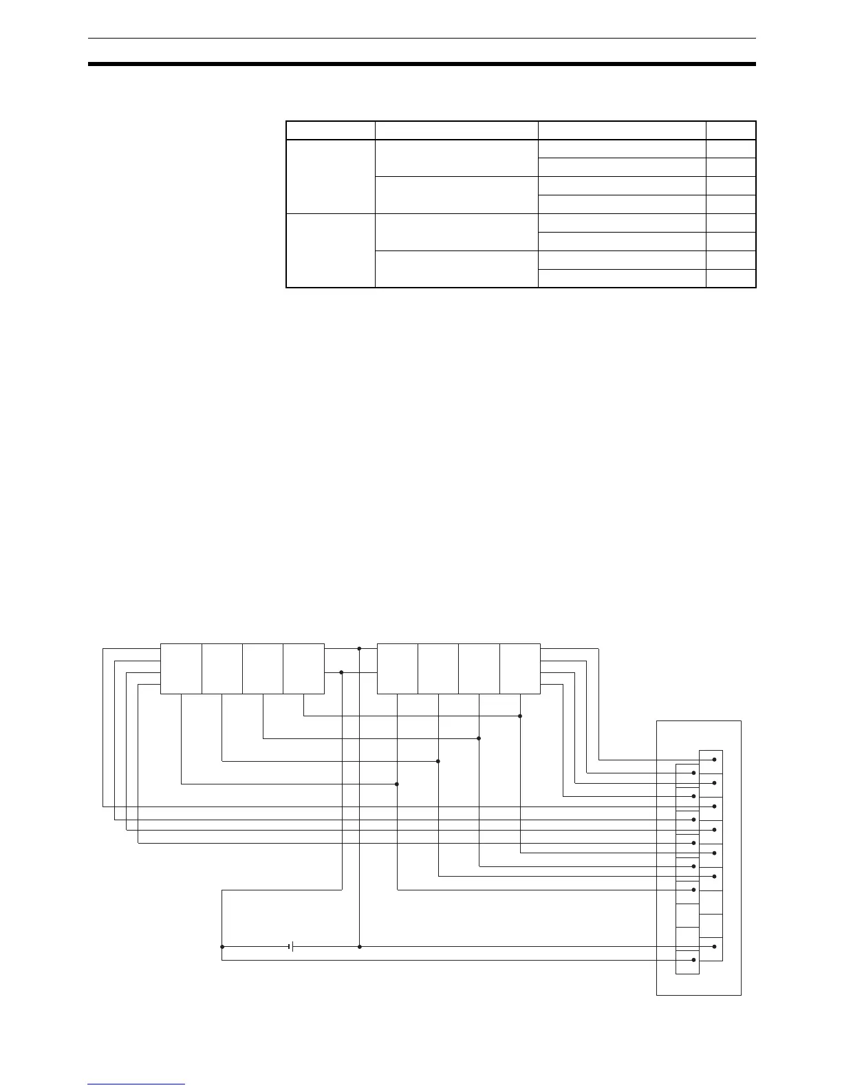
Hardware The 7-segment display is connected to an Output Unit as shown in the dia-
gram below. For 4-digit display, the data outputs (D0 to D3) are connected to
output points 0 through 3, and latch outputs (CS0 to CS3) are connected to
output points 4 through 7. Output point 12 (for 8-digit display) or output point 8
(for 4-digit display) will be turned ON when one round of data is displayed, but
there is no need to connect them unless required by the application.
Source data Display’s data input logic Display’s latch input logic C
4 digits (S) Same as Output Unit Same as Output Unit 0000
Different from Output Unit 0001
Different from Output Unit Same as Output Unit 0002
Different from Output Unit 0003
8 digits
(S, S+1)
Same as Output Unit Same as Output Unit 0004
Different from Output Unit 0005
Different from Output Unit Same as Output Unit 0006
Different from Output Unit 0007
1
3
5
7
9
11
13
15
COM
0
2
4
6
8
10
12
14
DC
OD212
D
0
D
1
D
2
D
3
V
DD
(+)
V
SS
(0)
LE3 LE2 LE1 LE0
D
0
D
1
D
2
D
3
V
DD
(+)
V
SS
(0)
LE3 LE2 LE1 LE0