EasyManua.ls Logo

Omron CQM1H - PROGRAM User Manual

Omron CQM1H - PROGRAM
602 pages
To Next Page IconTo Next Page
To Previous Page IconTo Previous Page
Page #484 background imageLoading...
Page #484 background image
459
Host Link Commands Section 6-5
Parameters Name, TC Number (Command)
In “Name, specify the name of the instruction, in four characters, for changing
the SV. In “TC number,” specify the timer/counter number used for the instruc-
tion.
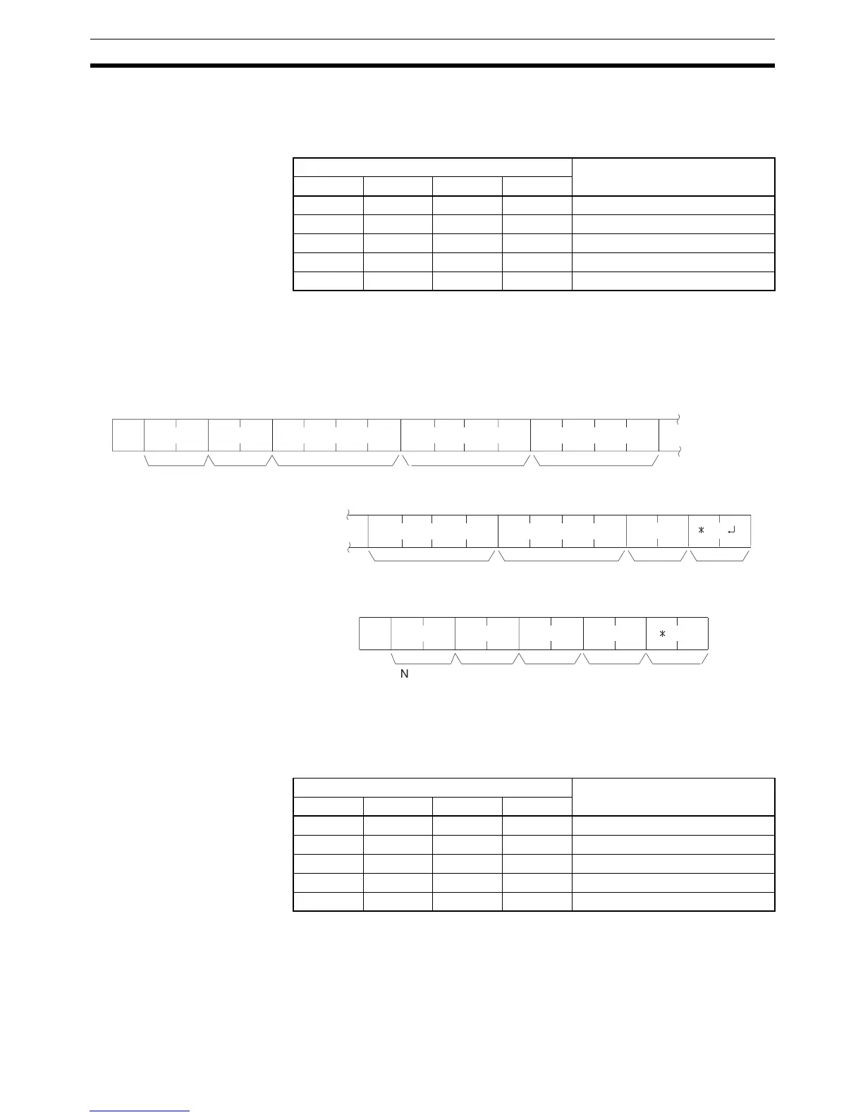
6-5-21 SV CHANGE 2 –– W$
Changes the contents of the second word of the TIM, TIMH(15), TTIM, CNT,
or CNTR(12) at the specified program address in the users program. This
can only be done with a program of up to 9,999 steps.
Command Format
Response Format An end code of 00 indicates normal completion.
Parameters Name, TC Number (Command)
In “Name, specify the name of the instruction, in four characters, for changing
the SV. In “TC number,” specify the timer/counter number used for the instruc-
tion.
Instruction name Classification
OP1 OP2 OP3 OP4
TI M(Space)TIMER
T I M H HIGH-SPEED TIMER
T T I M TOTALIZING TIMER
C N T (Space) COUNTER
C N T R REVERSIBLE COUNTER
OP4OP3OP2OP1@ W$ x 10
0
x 10
0
x 10
1
x 10
3
x 10
2
x 10
1
x 10
0
x 10
3
x 10
2
x 10
1
OP4OP3OP2OP1 x 10
0
x 10
3
x 10
2
x 10
1
*
Node No. Program address
(0000 to 9999)
Name TC number
(0000 to 0511)
Header
code
Operand SV TerminatorFCS
@ W$ x 16
0
x 10
0
x 10
1
x 16
1
*
Node
No.
Header
code
TerminatorFCSEnd code
Instruction name Classification
OP1 OP2 OP3 OP4
TI M(Space)TIMER
T I M H HIGH-SPEED TIMER
T T I M TOTALIZING TIMER
C N T (Space) COUNTER
C N T R REVERSIBLE COUNTER

Table of Contents

Question and Answer IconNeed help?

Do you have a question about the Omron CQM1H - PROGRAM and is the answer not in the manual?

Omron CQM1H - PROGRAM Specifications

General IconGeneral
I/O CapacityUp to 512 points
Power Supply100 to 240 VAC, 50/60 Hz or 24 VDC (depending on model)
Instruction SetBasic and advanced instructions
Operating Temperature0 to 55°C
Program Capacity7.2K to 15.2K steps
Communication PortsRS-232C
Expansion SlotsUp to 3 expansion units
TypeProgrammable Logic Controller (PLC)
CPU TypeRISC
Program Memory7.2K to 15.2K steps
I/O Points512 max
Expansion CapabilityUp to 3 expansion units
Data MemoryRAM (battery backup)

Summary

PRECAUTIONS

1 Intended Audience

Specifies the target personnel for this manual, requiring knowledge of electrical systems and FA systems.

2 General Precautions

Outlines user responsibilities for operating the product according to specifications and consulting representatives for specific applications.

3 Safety Precautions

Details critical safety warnings related to I/O refreshing, touching internal components, disassembly, and power supply handling.

5 Application Precautions

Provides essential safety guidelines for using the PC System, including grounding, power handling, and unit mounting.

SECTION 1 PC Setup and Other Features

1-1 PC Setup

Explains operating parameters for CQM1H control, including default values and how to change them.

SECTION 2 Inner Boards

2-1 High-speed Counter Board

Describes the functions, input modes, comparison operations, and external outputs of the High-speed Counter Board.

2-2 Pulse I/O Board

Details the Pulse I/O Board's support for two pulse inputs and two pulse outputs, including input modes and interrupts.

SECTION 3 Memory Areas

3-1 Memory Area Structure

Explains the memory areas used by the CQM1H PC, including IR, Work, Controller Link status, MACRO operand, Inner Board, Analog, High-speed Counter, and EM areas.

SECTION 4 Ladder-diagram Programming

4-1 Basic Procedure

Outlines the fundamental steps for writing a program, including obtaining I/O lists and drawing ladder diagrams.

4-4 Controlling Bit Status

Details instructions for controlling individual bit status: OUTPUT, OUTPUT NOT, SET, RESET, DIFFERENTIATE UP/DOWN, KEEP.

4-6 Programming Precautions

Provides essential precautions for drawing clear ladder diagrams and inputting programs, emphasizing instruction order and TR bits.

4-7 Program Execution

Describes the CPU Unit's program scan from top to bottom, checking conditions, and executing instructions.

SECTION 5 Instruction Set

SECTION 6 Host Link Commands

6-1 Host Link Command Summary

Provides a summary table of Host Link commands available for CQM1H communications.

6-4 Command and Response Formats

Details the formats for commands issued from the host computer and responses received from the PC.

6-5 Host Link Commands

Lists and describes various Host Link commands for reading and writing data in IR, SR, LR, HR, DM, EM, and AR areas.

SECTION 7 CPU Unit Operation and Processing Time

7-1 CPU Unit Operation

Explains the overall operation flowchart of the CQM1H CPU Unit and defines cycle time.

7-2 Power Interruptions

Details the CPU Unit's behavior during power interruptions and momentary power supply failures.

7-3 Cycle Time

Explains the processes involved in a single execution cycle and their respective processing times.

SECTION 8 Troubleshooting

8-2 Programming Console Operation Errors

Lists common error messages encountered when using the Programming Console and their appropriate responses.

Appendix A Programming Instructions

5-8 Ladder Diagram Instructions

Explains basic instructions like LOAD, AND, OR, and their combinations, including logic block instructions.

5-9 Bit Control Instructions

Covers instructions for controlling individual bit status: OUT, OUT NOT, SET, RESET, DIFU, DIFD, KEEP.

5-14 User Error Instructions: FAILURE ALARM AND RESET – FAL(06) and SEVERE FAILURE ALARM – FALS(07)

Describes instructions for outputting error numbers for operation, maintenance, and debugging, including non-fatal and fatal errors.

5-16 Timer and Counter Instructions

Details instructions for managing timers and counters, including TIM, TIMH, CNT, CNTR, TTIM, STIM, and CTBL.

5-29 Network Instructions

Explains instructions for communicating with other PCs via the Controller Link System, including SEND, RECV, and CMND.

5-30 Communications Instructions

Details instructions for serial communications, including RECEIVE (RXD), TRANSMIT (TXD), CHANGE SERIAL PORT SETUP (STUP), and PROTOCOL MACRO (PMCR).

Related product manuals