75
Using Heater Burnout, Heater Short, and Heater Overcurrent Alarms Section 3-10
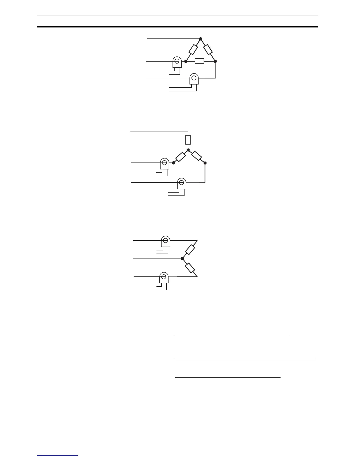
2. Star connecting lines: Refer to the following diagram for CT installation po-
sitions.
Note Heater voltage fluctuations are not considered here, so be take that
into account when setting the detection current.
3. V connecting lines: Refer to the following diagram for CT installation posi-
tions.
Note Heater voltage fluctuations are not considered here, so be take that
into account when setting the detection current.
3-10-3 Calculating Detection Current Values
• Calculate the set value using the following equation:
• To set the current for heater burnout when two or more heaters are con-
nected through the CT, use the value from when the heater with the small-
est current burns out. If all of the heaters have the same current, use the
value from when any one of them burns out.
CT
Load
Load
To CT input
Load
Load (such as a heater)
AC line
AC line
Product
To CT input
Product
CT
CT
Load
Load
Load
Load (such as a heater)
AC line
Product
To CT input
Product
To CT input
CT
CT
Load
Load
Load (such as a heater)
AC line
Product
To CT input
Product
To CT input
Heater Burnout Detection 1/2 set value =
Normal current value + Burnout current value
2
HS Alarm 1/2 set value =
Leakage current value (output OFF) + HS current value
2
Heater overcurrent 1/2 set value =
Normal current value + Overcurrent value
2

 Loading...


