50
Initial Setting Examples Section 3-1
3-1 Initial Setting Examples
Initial hardware setup, including the sensor input type, alarm types, control
periods, and other settings, is done using parameter displays. The O and M
Keys are used to switch between parameters, and the amount of time that you
press the keys determines which parameter you move to.
This section describes two typical examples.
Explanation of Examples
Example 1
25
0
C
in-t
0
cntl
onof
cntl
M
M
M
onof
in-l
0
in-h
100
Changing Parameters
A image means that there are parameters.
Continue pressing the M key to change parameters
until you reach the intended parameter.
Changing Numbers
Numeric data and selections in each
screen can be changed by using the
U and D keys.
100
20
onof
pid
run
stop
25
0
C
in-t
5
cntl
onof
alt1
2
25
100
C
r-s
run
al-1
20
C
M
M
M
M
M
M
Input type: 5 (K thermocouple,
−200°C to 1,300°C)
Control method: ON/OFF control
Alarm type: 2 (upper limit)
Alarm value 1: 20°C (deviation)
Set point: 100°C
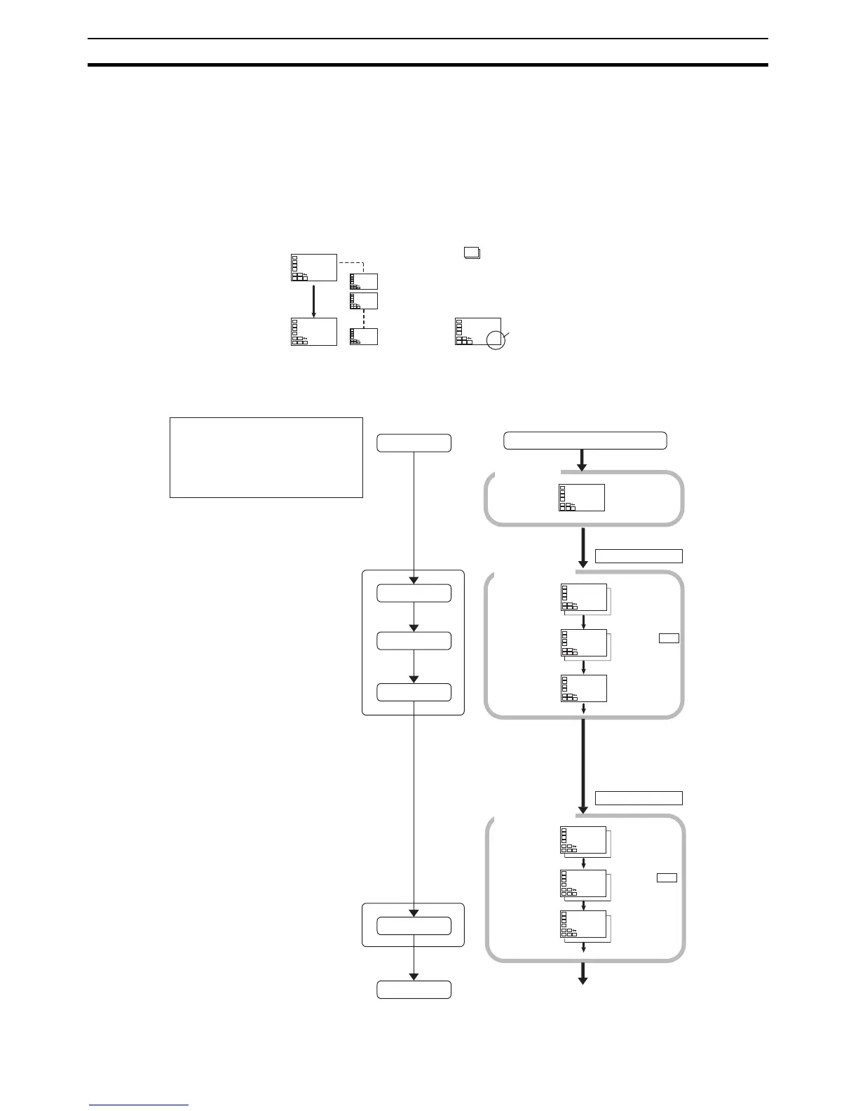
Setup Procedure
Power ON
Initial Setting
Level
Set input
specifications
Set control
specifications
Set alarm type
Operation
Level
Set alarm values
Start operation
Power ON
Operation
Level
PV/SP
Press the O key for
at least 3 s.
Control stops.
Initial Setting
Level
Input Type: 5
Check that
control method is
ON/OFF control.
ON/OFF
control:
PID
control:
Check alarm type.
Check input type.
Alarm 1 Type: 2
Press the O key for
at least 1 s.
Control starts.
Operation
Level
Use the U and
D keys to set the
SP to 100°C.
PV/SP:
Confirm that
control is running.
Running
Stopped:
Use the U and
D keys to set the
alarm value to
20°C.
Alarm Value 1:
Start operation.
An s.err
error will be
displayed if
the power
supply is
turned ON
before the
sensor is
connected.

 Loading...


