200
Initial Setting Level Section 5-7
• This parameter sets the type of sensor.
• When this parameter is changed, the set point limiter is changed to the
defaults. If the limiter must be specified, set the SP Upper Limit and SP
Lower Limit parameters (initial setting level) again.
• Set one of the set values from the following table.
The defaults are as follows:
Controllers with Thermocouple/Resistance Thermometer Universal
Inputs: 5 (K thermocouple)
Controllers with Analog Inputs: 0 (current input, 4 to 20 mA)
• If a platinum resistance thermometer is mistakenly connected while a set-
ting for other than a platinum resistance thermometer is in effect, S.ERR
will be displayed. To clear the S.ERR display, check the wiring and then
cycle the power.
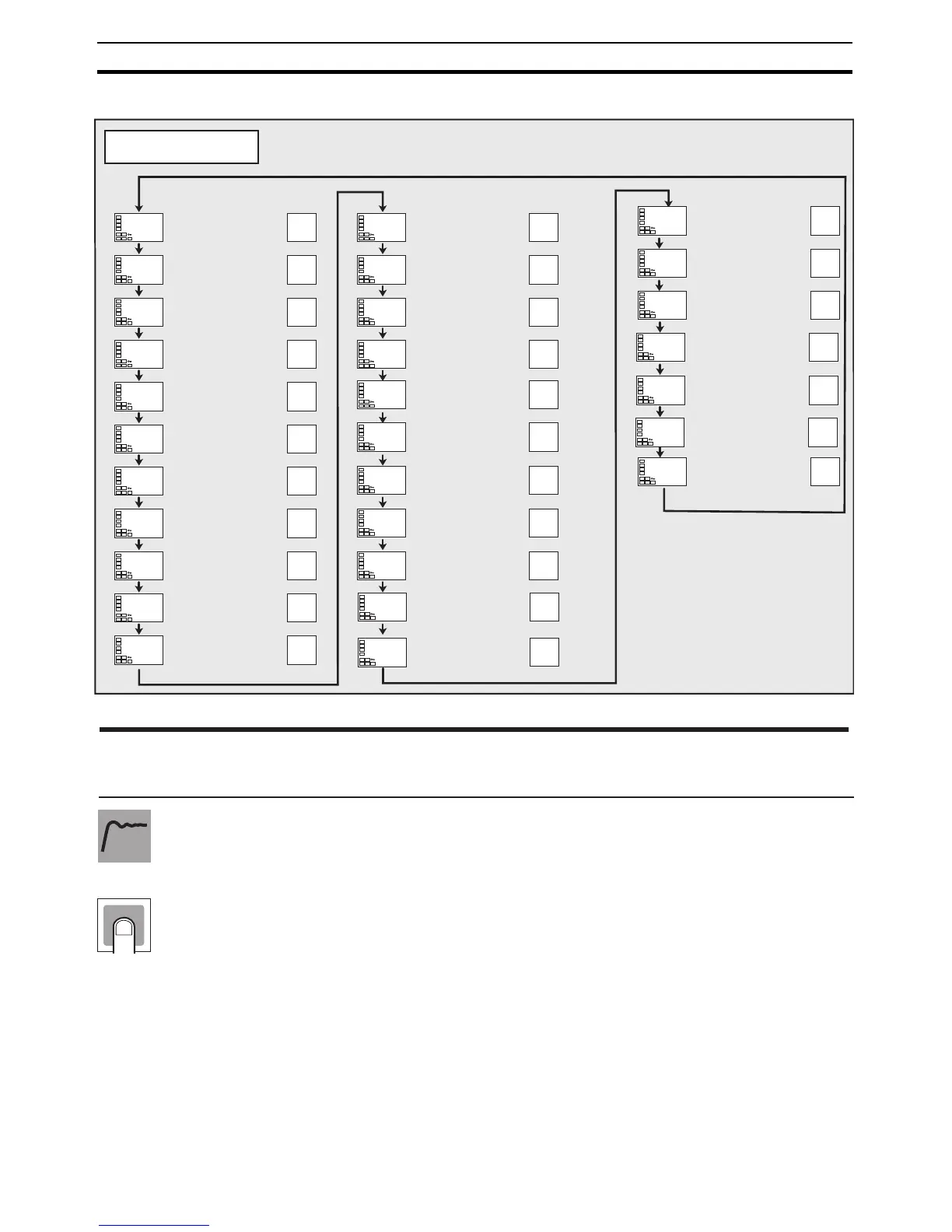
Initial Setting Level
M
M
M
M
M
M
M
M
M
M
M
M
M
M
M
M
M
M
M
M
M
M
M
M
M
M
M
M
in-l
0
dp
0
in-t
5
in-h
100
d-u
c
sl-h
1300
C
sl-l
-200
C
cntl
onof
s-hc
stnd
st
on
ptrn
off
cp
20
c-cp
20
oreV
or-r
alt1
2
Page Page
Input Type
Scaling Upper Limit
Scaling Lower Limit
Decimal Point
Temperature Unit
SP Upper Limit
SP Lower Limit
PID·ON/OFF
ST
Program Pattern
Control Period (Heating)
Control Period (Cooling)
Direct/Reverse
Operation
Alarm 1 Type
alt2
2
Alarm 2 Type
alt3
2
Alarm 3 Type
tr-t
off
Transfer Output Type
tr-h
100.0
Transfer Output Upper
Limit
tr-l
0.0
Transfer Output Lower
Limit
o1-t
4-20
Linear Current Output
amov
0
Move to Advanced
Function Setting Level
Standard or
Heating/Cooling
alh1
0.2
Alarm 1 Hysteresis
alh2
0.2
Alarm 2 Hysteresis
alh3
02
Alarm 3 Hysteresis
ev-m
1
Number of Multi-SP
Uses
ev-1
none
Event Input Assignment
1
ev-2
stop
Event Input Assignment
2
M
sqr
off
Extraction of Square
Root Enable
200
202
202
202
202
203
203
204
204
205
205
206
206
206
207
209
209
209
210
209
210
212
217
216
216
216
213
212
212
in-t Input Type
Function
Setting

 Loading...


