63
Determining PID Constants (AT, ST, Manual Setup) Section 3-8
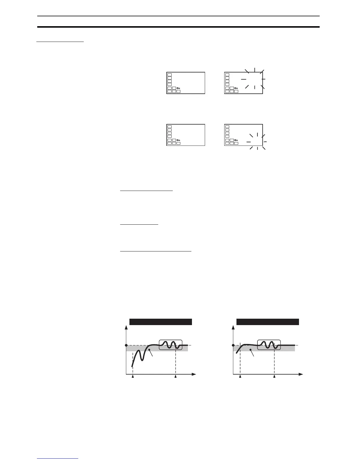
AT Operations AT is started when either at-2 (100% AT) or at-1 (40% AT) is specified for
the AT Execute/Cancel parameter. During execution, the AT Execute/Cancel
parameter on the No. 1 display flashes. When AT ends, the AT Execute/Can-
cel parameter turns OFF, and the No. 1 display stops flashing.
If you move to the operation level during AT execution, the No. 2 display
flashes to indicate that AT is being executed.
Only the Communications Writing, RUN/STOP, AT Execution/Cancel, and Pro-
gram Start parameters can be changed during AT execution. Other parame-
ters cannot be changed.
AT Calculated Gain
The AT Calculated Gain parameter sets the gain for when PID values are cal-
culated using AT. When emphasizing response, decrease the set value. When
emphasizing stability, increase the set value.
AT Hysteresis
The AT Hysteresis parameter sets the hysteresis when switching ON and OFF
for the limit cycle operation during auto-tuning.
Limit Cycle MV Amplitude
The Limit Cycle MV Amplitude parameter sets the MV amplitude for limit cycle
operation during auto-tuning.
Note This setting is disabled for 100% AT.
■ 40% AT
The width of MV variation in the limit cycle can be changed in the Limit Cycle
MV Amplitude parameter, but the AT execution time may be longer than for
100% AT. The limit cycle timing varies according to whether the deviation (DV)
at the start of auto-tuning execution is less than 10% FS.
at
off
at
at-2
AT Execute/Cancel
No. 1 displa

 Loading...


