4 - 9
4 Basic Operation
E5@C Digital Temperature Controllers User’s Manual (H174)
4-2 Initial Setting Examples
4
* If the Controller is equipped with HB/HS alarm detection, the default setting for the Auxiliary Output 1
Assignment is for heater alarms. Therefore, the alarm 1 function is disabled and the Alarm 1 Type is not
displayed. To enable alarm 1, set an output assignment to alarm 1. For details, refer to 4-6-3 Assigned
Output Functions (Assigning Control Outputs Is Not Supported for Position-proportional Models.).
Example 2
0
25
M
M
M
M
9
in-t
pid
cntl
2
alt1
150
25
M
off
st
20
cp
off
at
M
M
M
150
25
run
r-5
30
al-1
Set SP
9
20
30
2
150
onof
pid
on
off
off
run
stop
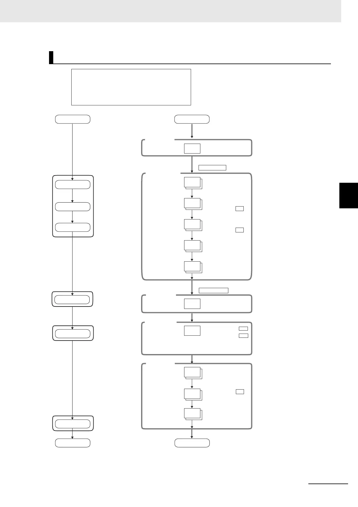
Input type: 9 (T thermocouple, −200°C to 400°C)
Control method: PID control
PID constants found using auto-tuning (AT).
Alarm type: 2 (upper limit)
Alarm value 1: 30°C
Set point: 150°C
Setup Procedure
Power ON
Initial Setting Level
Set input
specifications
Set control
specifications
Set alarm type
Adjustment Level
AT execution
(When PID control
is selected)
Operation Level
Set alarm value
Start operation
Power ON
Operation Level
PV/SP
Press the O Key for at least 3 s.
Control stops.
Initial Setting Level
Use the U and D
Keys to select the
input type.
Input Type:
Use the U and
D Keys to select
PID control.
ON/OFF control:
Use the U and
D Keys to set ST
to OFF.
To execute ST:
PID control:
To cancel ST:
Check the
control period.
Control Period
(Heat)
(Unit: Seconds)
Check the
alarm type.
Alarm 1 Type*:
For PID, set pid.
It is recommended that 20 seconds
be set for a relay output and 2
seconds for an SSR voltage output.
When a linear current output is
used, the Control Period parameter
cannot be used.
Press the O Key for at least 1 s.
Operation Level
Use the U and D
Keys to set the SP
to 150°C.
PV/SP:
Adjustment Level
Execute AT.
To execute 100%AT:
To cancel AT:
Press the O Key (for less than 1 s).
Press the O Key (for less than 1 s).
Control starts.
Operation Level
Confirm that the
set point is 150°C.
PV/SP
Confirm that
control is running.
Running
Stopped
Use the U and D
Keys to set the alarm
value to 30°C.
Alarm
Value 1
Start operation.
at-1
To execute 40%AT:
at-2
Operation Level
An s.err error will be displayed if
the power supply is turned ON
before the sensor is connected.
The TUNE indicator will
light during autotuning.

 Loading...