7 - 13
7 User Calibration
E5@C Digital Temperature Controllers User’s Manual (H174)
7-6 Calibrating the Transfer Output
7
7-6 Calibrating the Transfer Output
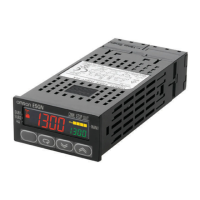
For Digital Controllers that have a transfer output, the trans-
fer output calibration display will be displayed after input cal-
ibration has been completed.
The E5CC-U, E5DC, E5DC-B, and E5GC do not have a
transfer output.
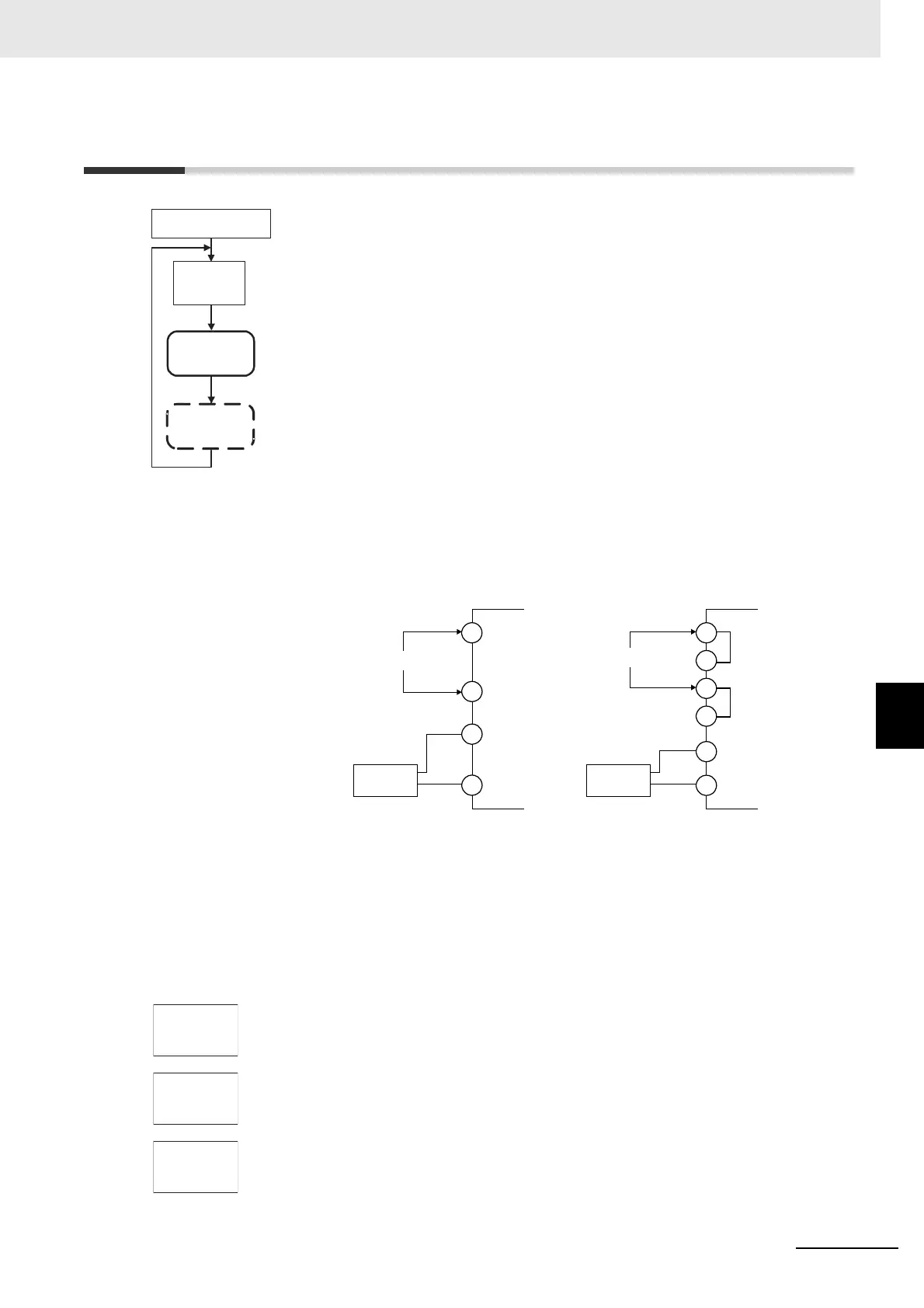
Use the following procedure to calibrate the transfer output for 4 to 20 mA.
1. Connect a DMM to the transfer output terminals.
2. Press the M Key to display the parameter for the transfer output.
3. The calibration display for 20 mA will be displayed. Press the U or D Key until
the DMM monitor value changes to 20 mA.
Press the M Key. The calibration settings will be temporarily registered.
4. The calibration display for 4 mA will be displayed. Press the U or D Key until the
DMM monitor value changes to 4 mA.
Press the M Key. The calibration settings will be temporarily registered.
Advanced Function
Setting Level
Transfer Output
Calibration
Main Input
Calibration
Input calibration
display
adj
30
M
M
M
M
Note: This is displayed only
for Digital Controllers
that have a transfer
output.
Input power supply
Input power supply
DMM
E5CC/E5EC/E5AC
+
−
DMM
E5@C-B
+
−
*
*
C
C
C'
D
D'
D
* Common
terminals are
indicated with
asterisks (*).
The terminal numbers are as follows:
• Transfer Output Terminals (Positive
and Negative)
E5CC: 17 and 18
E5EC/E5AC: 32 and 33
• Input Power Supply (C/D)
E5CC: 11 and 12
E5EC/E5AC: 1 and 2
The terminal numbers are as follows:
• Transfer Output Terminals (Positive
and Negative)
E5CC-B: 23 and 24
E5EC-B: 43 and 44
• Input Power Supply (C or C', and D
or D')
E5CC-B: 13 or 14, and 15 or 16
E5EC-B: 1 or 2, and 3 or 4

 Loading...