2 - 49
2 Preparations
E5@C Digital Temperature Controllers User’s Manual (H174)
2-2 Using the Terminals
2
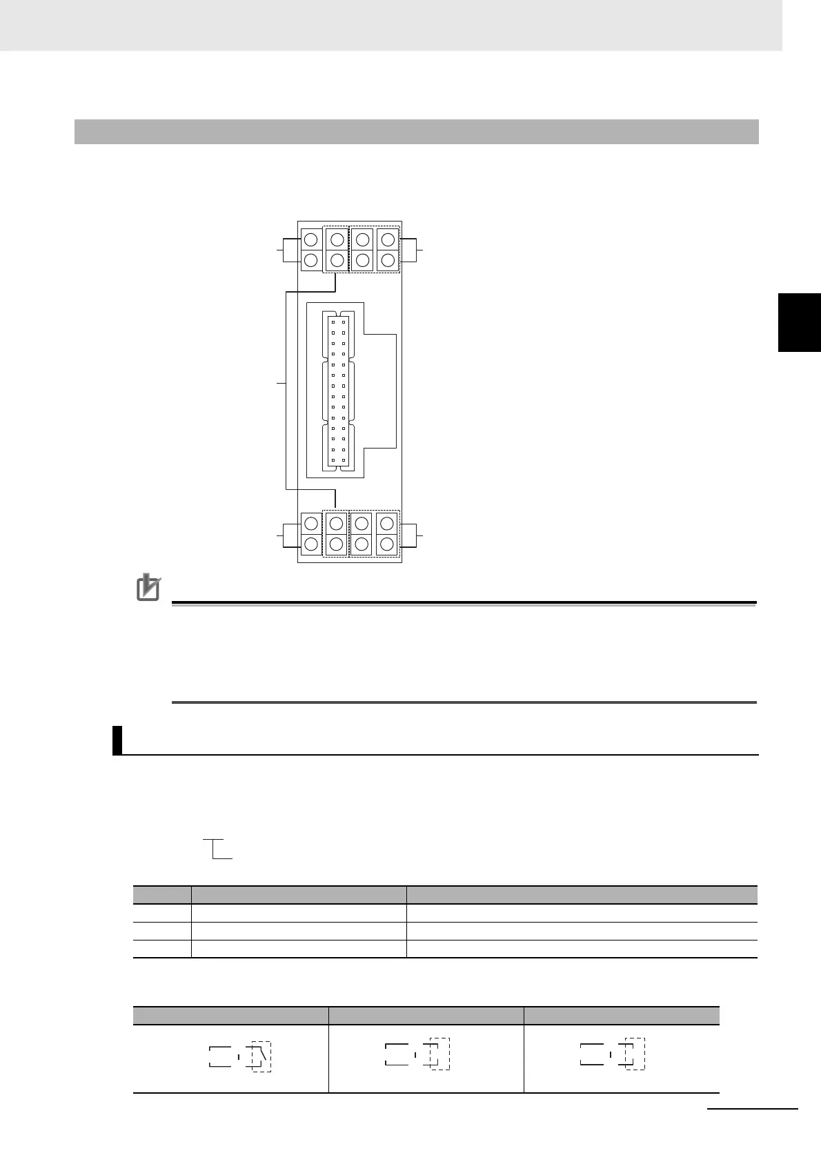
2-2-7 E5DC-B Terminal Block Wiring Example
Terminal Arrangement
The terminals block of the E5DC-B is divided into five types of terminals: control output 1, sensor input, auxiliary
outputs, input power supply, and options.
Precautions for Correct Use
• When you purchase the Digital Controller, it will be set for a K thermocouple (input type = 5). If
a different sensor is used, an input error (s.err) will occur. Check the setting of the Input Type
parameter.
• The terminal arrangement is different for the E5DC. Always check the terminal arrangement
diagram before wiring.
Model Numbers
The specification for control output 1 is given in the following location in the model number.
Terminal Details
2-2-7 E5DC-B Terminal Block Wiring Example
Control Output 1
Code Output type Specifications
RX 1 relay output 250 VAC, 3 A (resistive load)
QX 1 voltage output (for driving SSR) 12 VDC, 21 mA
CX 1 linear current output 4 to 20 mA DC or 0 to 20 mA DC with load of 500 Ω max.
RX QX CX
1
2
5
6
9
10
13
14
3
4
7
8
11
12
15
16
Input power supply
Control Output 1
Sensor input
Options
Auxiliary Outputs
E5DC-@@@@BM-@@@
Control Output 1
Relay
output
Control Output 1
C
D
+
-
Control output 1
Voltage output
(for driving SSR)
C
D
Control Output 1
Linear current
output
+
-
C
D

 Loading...