7 - 15
7 User Calibration
E5@C Digital Temperature Controllers User’s Manual (H174)
7-7 Checking Indication Accuracy
7
7-7 Checking Indication Accuracy
• After calibrating the input, be sure to check the indication accuracy to make sure that the
calibration has been executed correctly.
• Operate the E5@C in the process value/set point monitor mode.
• Check the indication accuracy at the following three values: upper limit, lower limit, and mid-point.
• To check the range of an infrared sensor, set the input type parameter to 6 (i.e., a K
thermocouple) and input a voltage that is equivalent to the starting power of a K thermocouple.
Thermocouple or Infrared Temperature Sensor
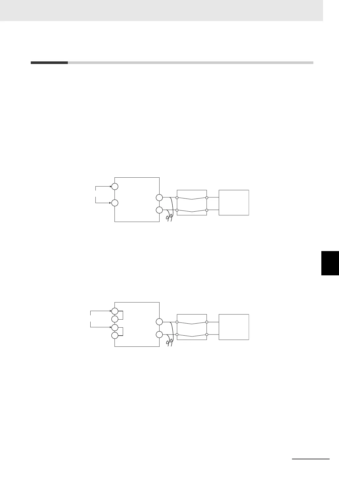
• Preparations
The diagram below shows the required device connections. Make sure that the E5@C and cold
junction compensator are connected by a compensating conductor for the thermocouple that is to
be used during actual operation.
• Operation
Make sure that the cold junction compensator is at 0°C, and set the STV output to the voltage
equivalent of the starting power of the check value.
The cold junction compensator and compensation conductor are not required when an external
cold junction compensation method is used.
Input power supply
Cold junction compensator
Compensating conductor
−
STV
+
*
*
* Common terminals are indicated with asterisks (*).
C
D
C
C'
D
D'
STV
+
E5CC, E5CC-U, E5EC, E5AC, E5DC, E5DC-B, or E5GC
E5CC-B/E5EC-B
Input power supply
Cold junction compensator
Compensating conductor
−
The terminal numbers are as follows:
• Input Terminals (Negative and Positive)
E5CC: 5 and 6
E5CC-U: 2 and 1
E5EC/E5AC: 23 and 24
E5DC: 13 and 14
E5DC-B: 15 and 16
E5GC: 11 and 12
• Input Power Supply (C/D)
E5CC: 11 and 12
E5CC-U: 10 and 11
E5EC/E5AC: 1 and 2
E5DC: 1 and 2
E5DC-B: 1 and 2
E5GC: 1 and 2
The terminal numbers are as follows:
• Input Terminals (Negative and Positive)
E5CC-B: 7 and 8
E5EC-B: 31 and 32
• Input Power Supply (C or C', and
D or D')
E5CC-B: 13 or 14, and 15 or 16
E5EC-B: 1 or 2, and 3 or 4

 Loading...