7 - 3
7 User Calibration
E5@C Digital Temperature Controllers User’s Manual (H174)
7-2 Parameter Structure
7
7-2 Parameter Structure
• To execute user calibration, enter the password "1201" at the Move to Calibration Level parameter in
the Advanced Function Setting Level. The mode will be changed to the calibration mode, and adj
will be displayed.
• The Move to Calibration Level parameter may not be displayed when the user is doing the calibration
for the first time. If this happens, set the Initial Setting/Communications Protect parameter in the
Protect Level to 0 before moving to the Advanced Function Setting Level.
• The calibration mode is ended by turning the power OFF.
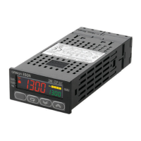
• The parameter calibrations in the calibration mode are structured as shown below.
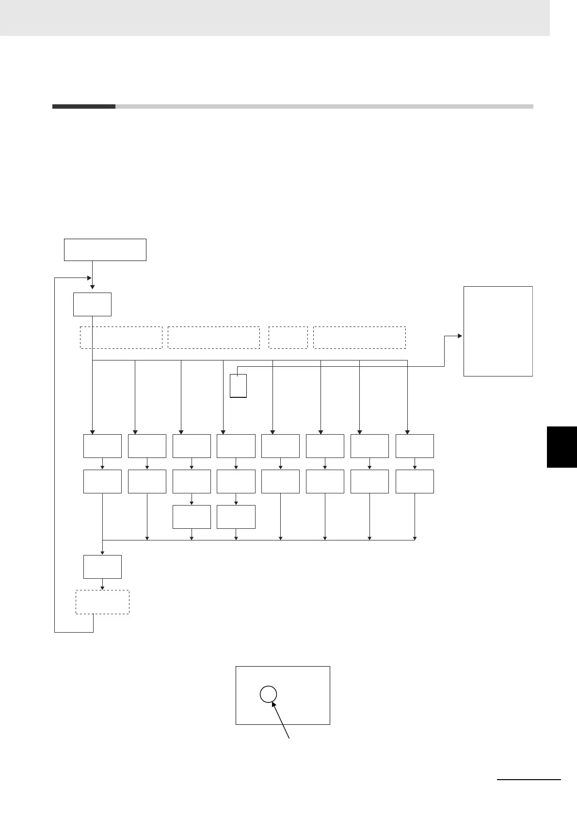
When calibration has been performed after purchase, the user calibration information shown in the
following illustration will be displayed when moving to the Calibration Level.
0: Pt100
1: Pt100
2: Pt100
3: JPt100
4: JPt100
5: K
7: J
11: E
12: L
15: N
19: W
20: PLII
25: 4 to 20 mA
26: 0 to 20 mA
27: 1 to 5 V
28: 0 to 5 V
29: 0 to 10 V
* This function is displayed only for a Digital Controller that has a transfer output.
The E5CC-U, E5DC, E5DC-B, and E5GC do not have a transfer output.
30: 0 to 50 mV*1
M
M
M
M
M
M
M M
M
M
M
M
M
M
M
M
MM
MM
p 10
4543
str
no
p 10
4543
t -6
2988
t -6
0200
bia5
35b8
bia5
35b8
a 1
4677
1V 1
5ac0
2V 1
4ad9
p390
e20c
p280
e26b
t 54
b9a5
t -6
2988
t 54
b9a5
t 24
e220
a 20
c8e7
1V 5
c7c3
2V10
b104
adj
30
Advanced Function
Setting Level
Display moves automatically according to input type.
Resistance
thermometer
Thermocouple or infrared
temperature sensor
6: K
8: J
9,10: T
13,14: U
16: R
17: S
18: B
21: K140F/60C
22: K240F/120C
23: K280F/140C
24: K440F/220C
Transfer output
calibration
Current
input
Voltage input
*This range can be used only for
E5CC-U Digital Controllers and only
if they are manufactured in May
2014 or later (version 2.2 or higher).
.adj
30
A dot is displayed.

 Loading...