5 Advanced Operations
5 - 58
E5@C Digital Temperature Controllers User’s Manual (H174)
5-19 Displaying PV/SV Status
PV Status Display Function (Advanced Function Setting Level)
The PV on the No. 1 display in the PV, PV/SP, PV/Manual MV, or PV/SP Manual MV Display and the
control or alarm status specified for the PV status display function are alternately displayed in 0.5-s
cycles.
*1
• PV
• PV/SP
*2
• PV/Manual MV (Valve Opening)
• PV/SP/Manual MV (Valve Opening)
*1 This includes the displays specified with the PV/SP No. 1 and PV/SP No. 2 Display Selection parameters.
*2 This includes when the PV/SP is selected for the Monitor/Setting Item parameter.
Note: The default is OFF.
* Selection is possible only with the E5DC, E5DC-B and E5GC. (The E5DC must be manufactured in July
2014 or later (version 2.2 or higher).)
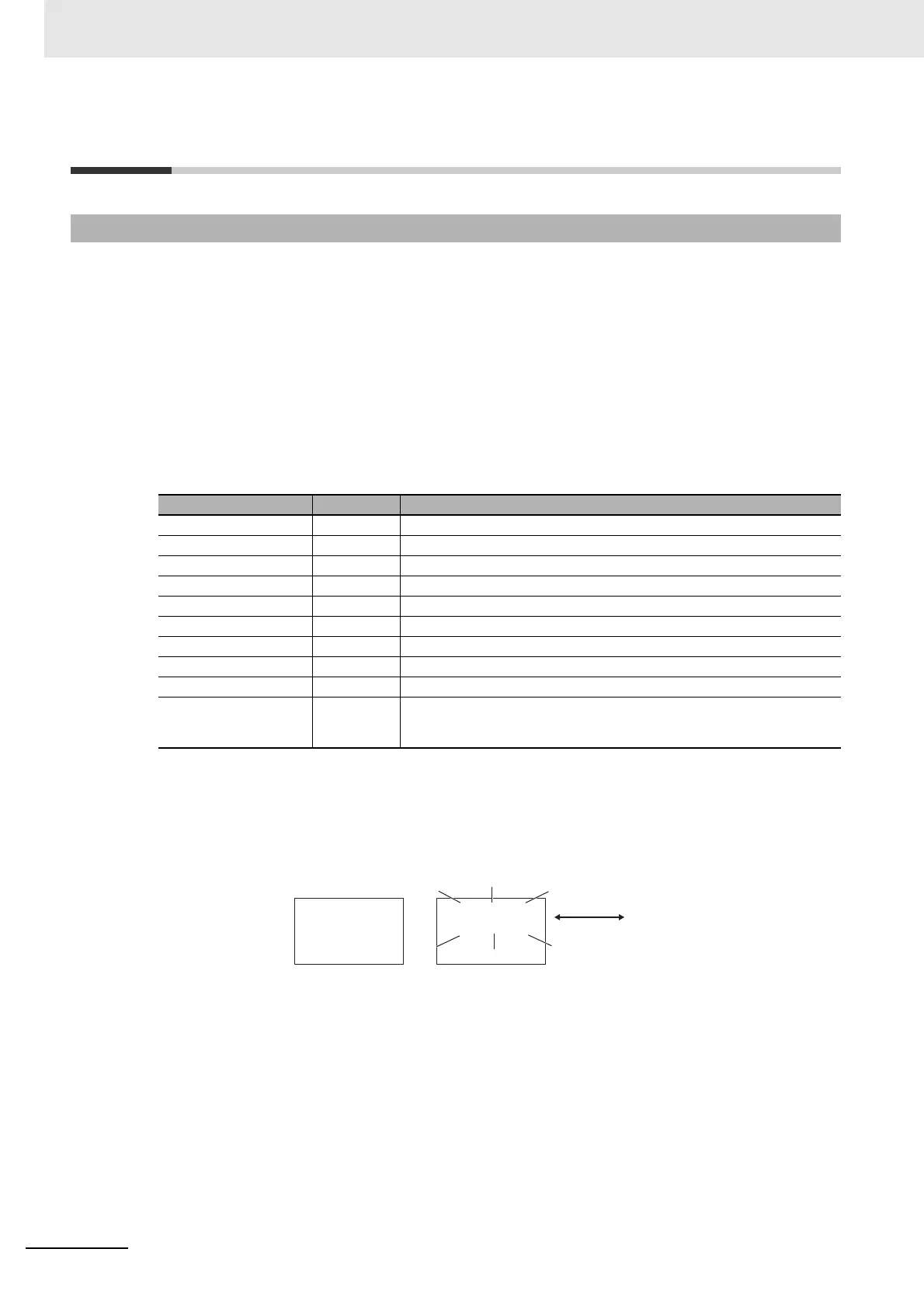
Example: When STOP Is Selected for the PV Status Display Function
SV Status Display Function (Advanced Function Setting Level)
The SP, Manual MV, or blank on the No. 2 display in the PV/SP, PV, or PV/Manual MV Display and
the control or alarm status specified for the SV status display function are alternately displayed in
0.5-s cycles.
*1
• PV
• PV/SP
*2
• PV/Manual MV (Valve Opening)
• PV/SP/Manual MV (Valve Opening)
*1 This includes the displays specified with the PV/SP No. 1 and PV/SP No. 2 Display Selection parameters.
*2 This includes when the PV/SP is selected for the Monitor/Setting Item parameter.
5-19-1 PV and SV Status Display Functions
Set value Display Function
OFF off No PV status display
Manual manu MANU is alternately displayed during manual control.
Stop stop STOP is alternately displayed while operation is stopped.
Alarm 1 alm1 ALM1 is alternately displayed during Alarm 1 status.
Alarm 2 alm2 ALM2 is alternately displayed during Alarm 2 status.
Alarm 3 alm3 ALM3 is alternately displayed during Alarm 3 status.
Alarm 4 alm4 ALM4 is alternately displayed during Alarm 4 status.
Alarm 1 to 4 OR status alm ALM is alternately displayed when Alarm 1, 2, 3, or 4 is set to ON.
Heater Alarm ha HA is alternately displayed when an HB alarm or HS alarm is ON.
Status display mes-
sage* wr
While one or more of the work bits (WR1 to WR8) is ON, the message
for the highest bit number that is ON is alternately displayed with the
corresponding bit number.
25
100
stop
100
25
Normal
PV/SP
When RUN/STOP
is STOP
Alternating
display

 Loading...