7 User Calibration
7 - 16
E5@C Digital Temperature Controllers User’s Manual (H174)
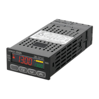
Resistance Thermometer
• Preparations
The diagram below shows the required device connections.
• Operation
Set the 6-dial variable resistor to the resistance that is equivalent to the test value.
Input power supply
6-dial variable
resistor
A
B
B
A
B
B
*
*
* Common terminals are indicated with asterisks (*).
E5CC, E5CC-U, E5EC, E5AC, E5DC, E5DC-B, or E5GC
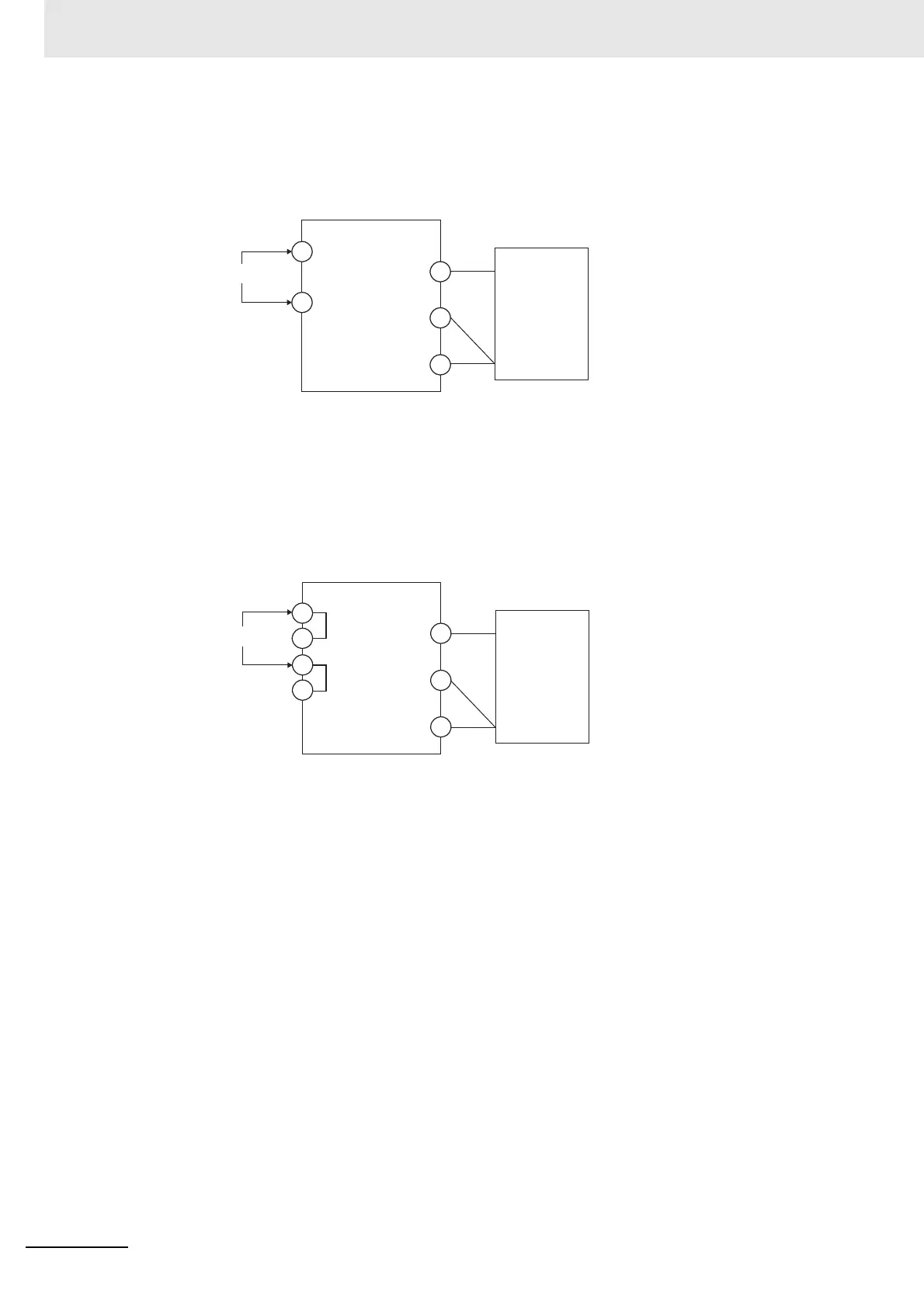
E5CC-B or E5EC-B
C
D
C
C'
D
D'
Input power supply
6-dial variable
resistor
The terminal numbers are as follows:
• Input Terminals (A/B/B)
E5CC: 4, 5, and 6
E5CC-U: 3, 2, and 1
E5EC/E5AC: 22, 23, and 24
E5DC: 12, 13, and 14
E5DC-B: 11, 15, and 16
E5GC: 10, 11, and 12
• Input Power Supply (C/D)
E5CC: 11 and 12
E5CC-U: 10 and 11
E5EC/E5AC: 1 and 2
E5DC: 1 and 2
E5DC-B: 1 and 2
E5GC: 1 and 2
The terminal numbers are as follows:
• Input Terminals (A/B/B)
E5CC-B: 6, 7, and 8
E5EC-B: 30, 31, and 32
• Input Power Supply (C or C', and D or D')
E5CC-B: 13 or 14, and 15 or 16
E5EC-B: 1 or 2, and 3 or 4

 Loading...