Chapter 6: Connectivity
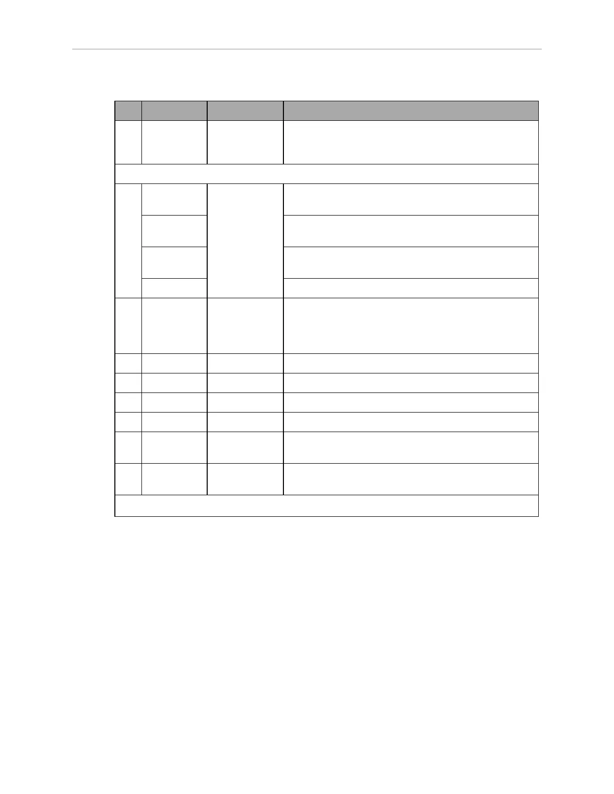
Table 6-3 Connectors on the LD-250 Core's Rear Upper Interface Panel
ID Connection Type Description
A Lights Mini-Fit 2 x 3 Connect to a supplied splitter that powers a buzzer
using a default configuration, and provides power for a
user-supplied light tower with 3 lights.
The following four functions are pins on the User Interface connector.
B Brake-
release
Mini-Fit 2 x 7 Pins for user-supplied brake release
ON Pins for user-supplied ON button; same function as
Operator Panel ON
OFF Pins for user-supplied OFF button; same function as
Operator Panel OFF
E-STOP Pins for user-supplied E-Stop. Jumper if not used.
C User
Bumpers
Mini-Fit 2 x 4 Payload structure bumpers, user-supplied, connected
between E-STOP_SRC and USER_BMP# (for each of the
6 inputs). Contacts 1 - 3 are for a front bumper, 4 - 6 for
rear. Contacts should be 12 V @ 10 mA.
D Aux Power Mini-Fit 2 x 3 5, 12, and 20 VDC Outputs
E User Power Mini-Fit 2 x 6 Battery and switched battery power
F Sonar 2 DB9M Not used
G HMI Panel HDB15F Operator screen, E-Stop, Brake_Rel, ON, OFF.
H Joystick DB9F Directly connected to the externally-mounted Joystick
port
I Maint LAN RJ45,
Shielded
Directly connected to the externally-mounted Main-
tenance Ethernet, Auto-MDIX.
a
Molex Mini-Fit Jr™ 5557 series receptacles.
Joystick Connector
The LD-250 Core's Joystick DB9F connector is replicated on the AMR's exterior under a small
door on the rear (see LD-250 Features. on page 12)
Use the Joystick for manual driving and mapping.
Power Connections
The LD-250's battery provides conditioned 5, 12, and 20 VDC, and raw (battery) 22 - 30 VDC
power to the LD-250’s accessory electronics, including the LD-250 Core and laser LIDAR (Light
Detection And Ranging).
All power connectors are Mini-Fit
®
.
Refer also to Power Consumption on page 79
20472-000 Rev B LD-250 Platform User's Guide 101

 Loading...


