Chapter 3: Setup
AMR’s to maneuver. Obstacles close to the docking station might prevent successful
docking.
l
Each docking station requires an adjacent wall power outlet. In highly-automated fleet
environments, consider using a redundant power supply.
IMPORTANT: If you do not use appropriate fasteners for sustained use, the
docking station might move during docking attempts, causing docking and char-
ging failures. The maximum fastener diameter is 6 mm (0.25").
Docking Station Features and Parts
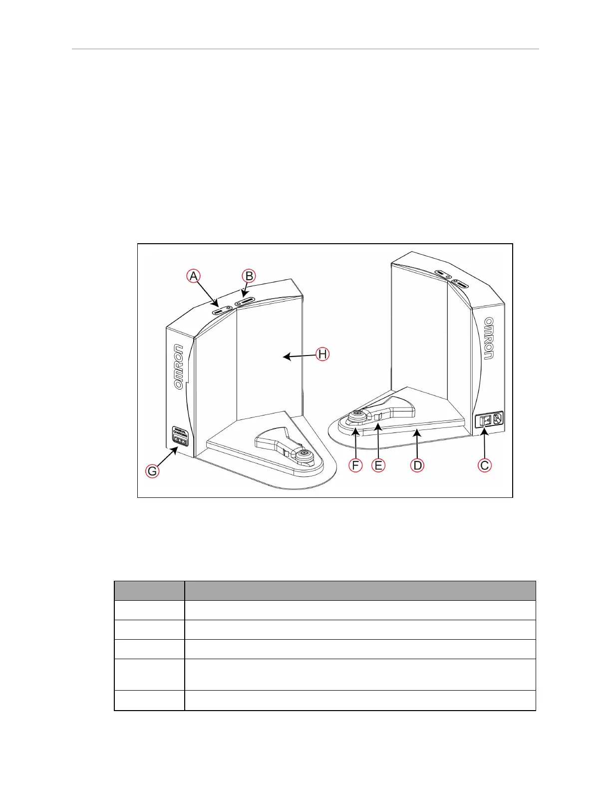
Figure 3-13 shows the exterior features and parts of the docking station. This figure does not
include the optional floor plate for free-standing installation.
Figure 3-13 Docking Station—Features and Parts
Table 3-2 describes the parts of the docking stations that are of interest to the user.
Table 3-2 Description of the Docking Station Features and Parts
Callout Description
A Power indicator LED (blue).
B Charging indicator LED (amber).
C Power inlet socket and power switch.
D Charging paddle. This is articulated and spring loaded to make good contact
with the AMR's charging contacts.
E Electrical contacts.
20472-000 Rev B LD-250 Platform User's Guide 59
 Loading...


