132 LD-250 Platform User's Guide 20472-000 Rev B
7.5 Other Controls and Indicators
LD-250 Core Status Indicators
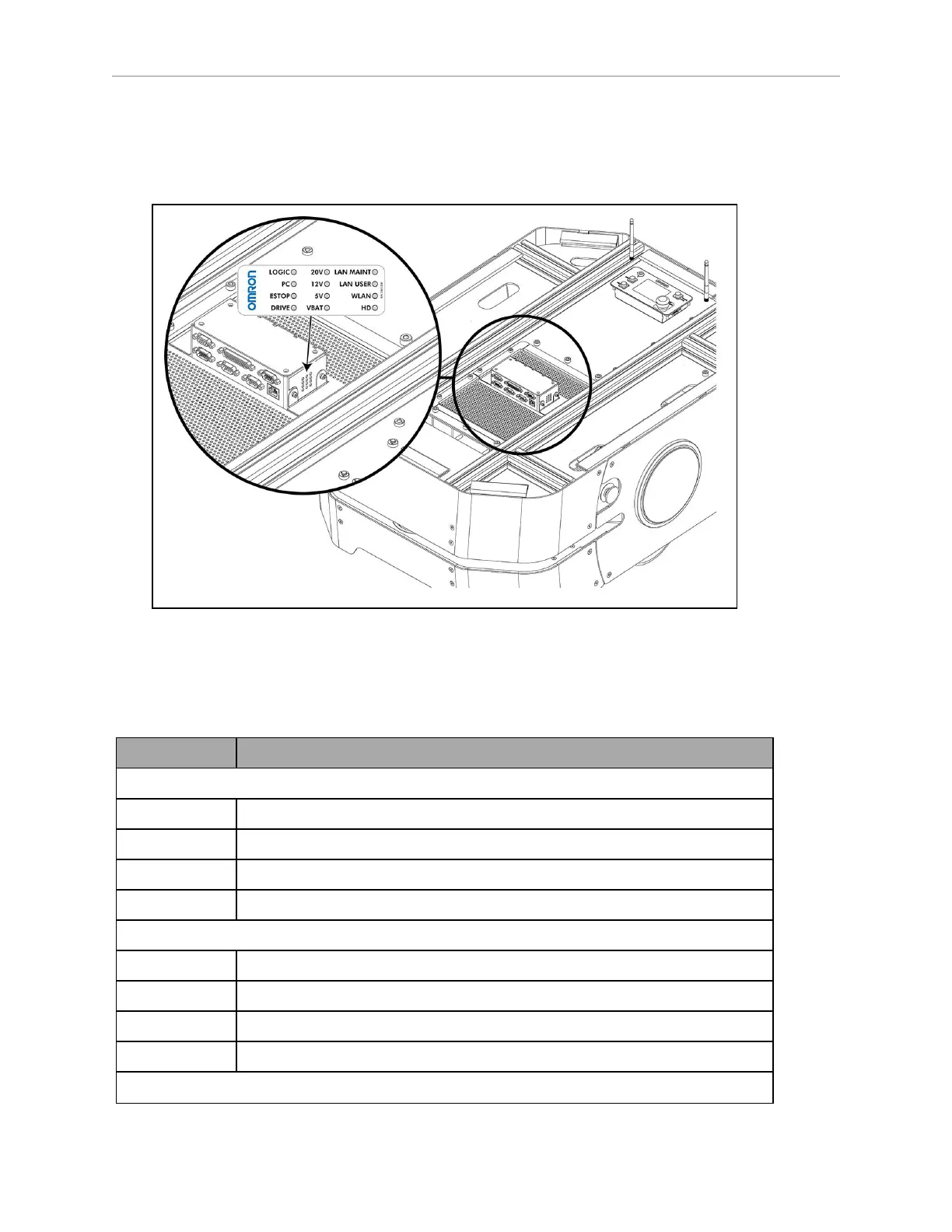
The left side of the LD-250 Core has 12 indicator LEDs that indicate subsystem status. Labels
on the payload bay provide a description of the LEDs.
Figure 7-7 LD-250 Core LEDStatus LEDand Identification Label
Table 7-3 provides descriptions for the status LEDs:
Table 7-3 LD-250 Core Status LED Description
LEDIndicator Meaning
Left Column
LOGIC The microcontroller has power
PC The LD-250 Core and the servo controller are communicating
E-STOP An E-Stop button is activated
DRIVE The drive wheels are under servo control
Middle Column
20V 20 V power is available
12V 12 V power is available
5V 5 V power is available
VBAT Unregulated battery power is available
Right Column
 Loading...


