Chapter 3: Setup
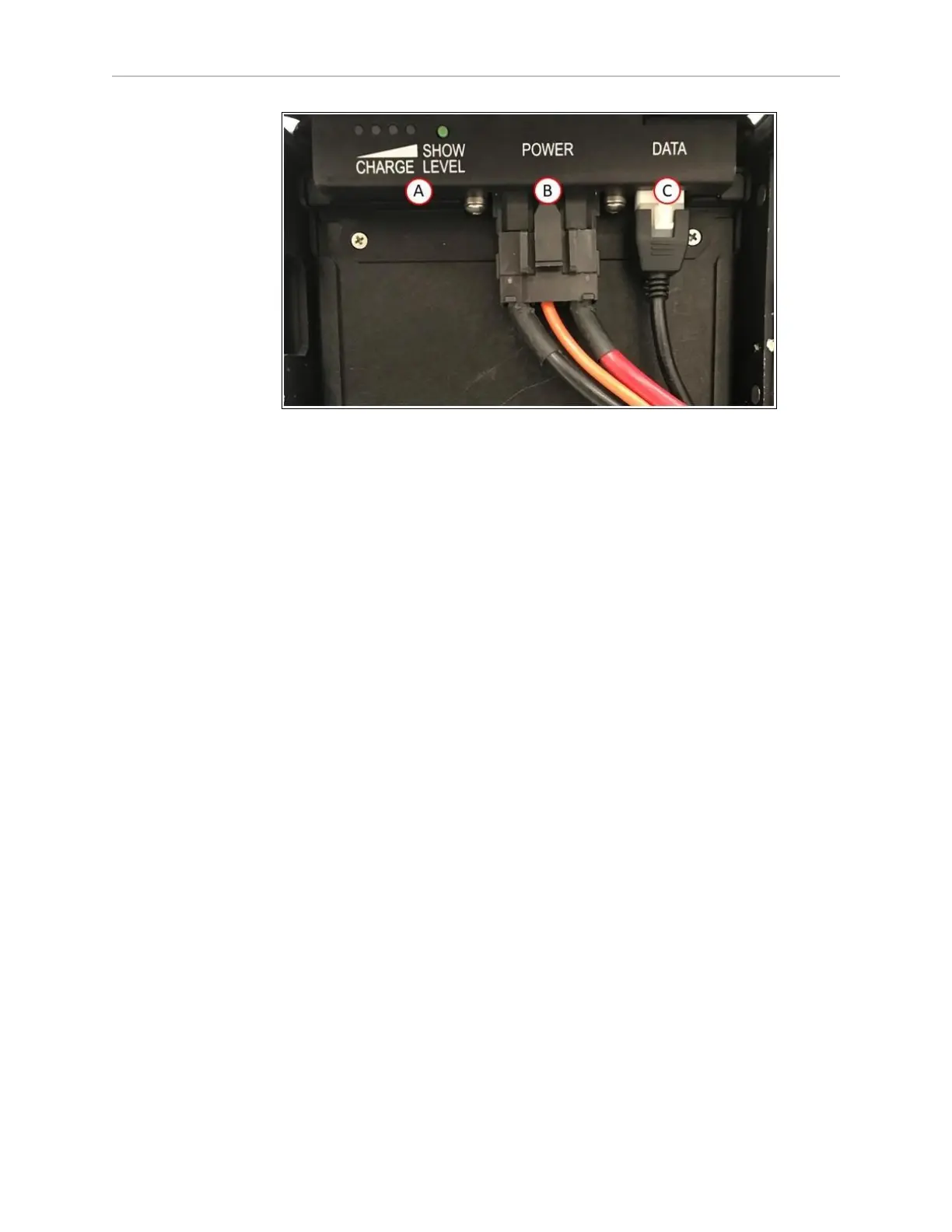
Figure 3-11 Battery Cable Connectors, (A) Battery Charge Level, (B) Power Connector, (C) Data
Connector
3.
Close the battery compartment door to secure the battery in place and to prevent it from
shifting inside the compartment. Lock the door to prevent unauthorized access.
4.
Reinstall the LD-250's battery access skin and close the latch to secure it in place.
Do not power on the LD-250 until you have read the appropriate sections of this user's guide.
3.6 Attaching the Payload Structure and Options
Attach the Payload Structure
At this point in AMR set up, attach your payload structure to the load-bearing bars located
beneath the top cover. Omron provides only the mount point options described in: Payload
Dimensions and Design on page 80.
For information about power, data signal, and warning light connections, see: Connectivity on
page 93.
Attach LD-250 Options
If you ordered optional devices such as Acuity Localization that shipped separately, attach
them next. See: Optional Connections on page 91.
E-Stop Jumper on the LD-250 Core
The LD-250 Core requires either of the following attached to the E-STOP port (User Interface):
l
A jumper (part number 12730-000L).
l
User-supplied E-Stop button.
See: User Interface (Brake and E-Stop) on page 103.
20472-000 Rev B LD-250 Platform User's Guide 57
 Loading...


