86 LD-250 Platform User's Guide 20472-000 Rev B
5.2 Considerations
AMR Coordinate System
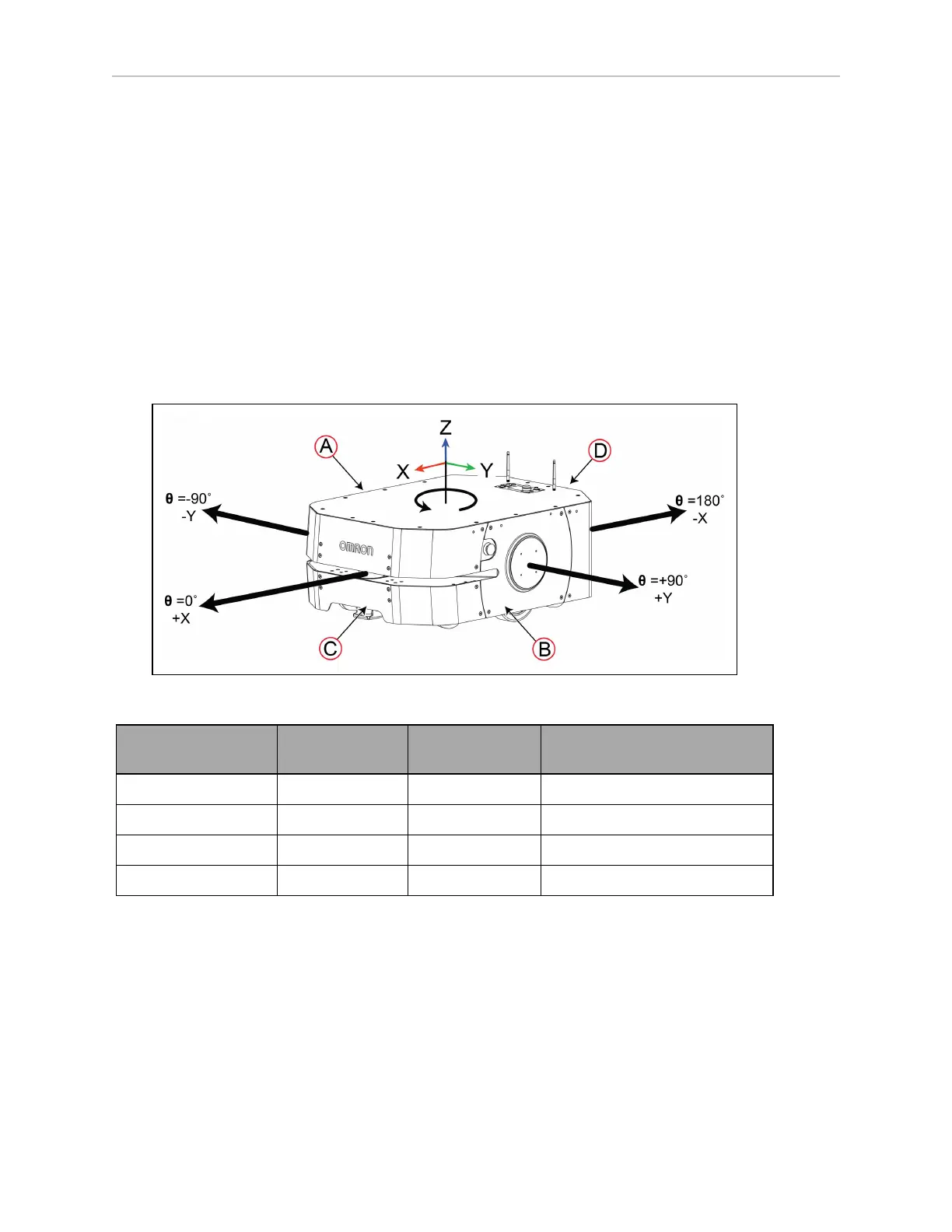
Omron AMRs use the X, Y, Z and Theta (θ coordinate system. This information is relevant for
some of the procedures used in this manual, such as identifying which are the left or right
skins. For example, the joystick port is located in the rear left skin. The origin of the coordinate
system is the AMR's center of rotation, not its geometric center.
Coordinates are required for procedures such as installing and configuring options such as
lasers and the Acuity camera, and for understanding the center of gravity envelope. The
AMR's coordinates also relate to the map coordinates.
The rotation value Theta (θ) specifies the AMR's angle of rotation, which determines its head-
ing, or direction of travel.
The vertical coordinate (Z) is required when you calculate the mount position of options (such
as side lasers). You then specify the position of the option in MobilePlanner.
Figure 5-5 AMR Coordinate System
Callout AMR Reference
Theta θ
(Rotation)
X, Y
Coordinate
A Right side -90 degrees Negative Y
B Left side +90 degrees Positive Y
C Front 0 degrees Positive X
D Rear 180 degrees Negative X
See: Dimension Drawings on page 191 for the location of the AMR's center of rotation.
Center of Gravity (CG)
Keep your payload structure's center of gravity (CG)centered over the LD-250's own center of
gravity and as low (close to the LD-250's top) as possible. This provides optimum stability, par-
ticularly when the LD-250 crosses raised thresholds or irregularities in the floor.
See: Dimension Drawings on page 191 for information that will help you design and locate the
payload, in particular:
 Loading...


