Chapter 6: Connectivity
Callout Description Callout Description
A Standard Equipment E Load
B User-Supplied Equipment F Outputs 1-16
C Wiring Terminal Block G Equivalent Circuit
D Typical User Loads
Analog I/O
The LD-250 Core's Analog I/O HDB15M connector is reserved for internal use only. Contact
your local Omron Support before attempting to use these circuits.
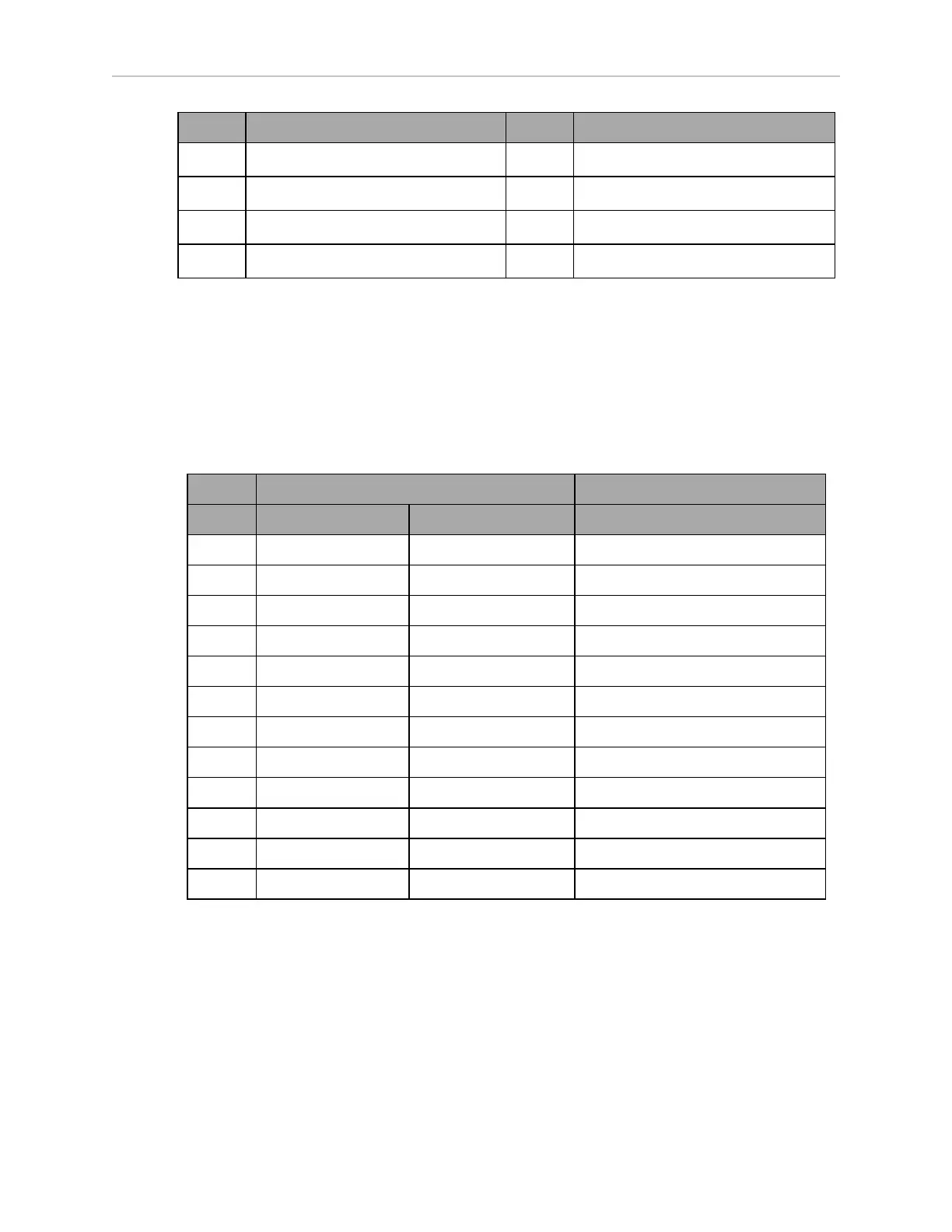
Aux Sensors
The LD-250 Core's Aux Sensors HDB15M connector provides circuits used by the Low Front
Laser and optional Side Lasers (tilted lasers).
Designation
Pin No. Hardware Software Notes
1 RS232_VERT1_TXD /dev/ttyUSB5 (side lasers)
2 RS232_VERT2_TXD /dev/ttyUSB6 (side lasers)
3 RS232_FOOT_TXD /dev/ttyUSB7 (low front laser)
4 5V_SW1 USB_1_and_2_Power 5 V @ 1 A (shared with USB port 1)
5, 10 SW_20V_VERT Vertical_Laser_Power 20 V @ 300 mA (side lasers)
6, 7, 8 GND
9 5V_SW2 USB_1_and_2_Power 5 V @ 1 A (shared with USB port 2)
11 RS232_VERT1_RXD /dev/ttyUSB5 (side lasers)
12 RS232_VERT2_RXD /dev/ttyUSB6 (side lasers)
13 RS232_FOOT_RXD /dev/ttyUSB7 (low front laser)
14 5V_SW3 USB_3_Power 5 V @ 1 A (shared with USB port 3)
15 SW_20V_FOOT Foot_Laser_Power 20 V @ 150 mA (low front laser)
20472-000 Rev B LD-250 Platform User's Guide 99

 Loading...


