9 Reconnect the Ethernet cable on the AMR to the rear port of the Passthrough connector.
10 Route the ribbon cable on the AMR through the oval hole on the blanking plate and pull out the
ribbon cable.
11
Fasten the blanking plate in the location where the Operator Panel was mounted using the five
M5 screws.
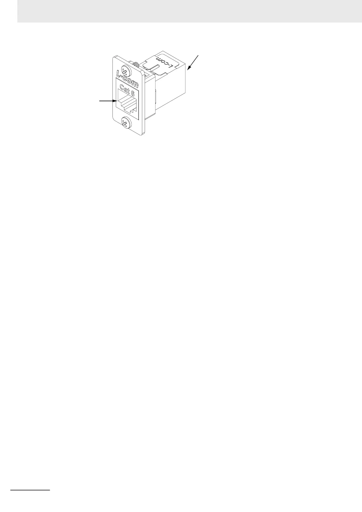
12 Connect one end of the Ethernet patch cable to the front port of the Passthrough connector.
13 Mount the Operator Panel on the user-specified location.
14 Route the ribbon cable and Ethernet patch cable to the new location of the Operator Panel.
Route cables in a path that avoids chaffing, pinching, flexing, straining, or damage. Avoid rout-
ing cables near high current conductors or other devices that can induce transient signals.
15 Connect the ribbon cable and the other end of the Ethernet patch cable to the rear of the Oper-
ator Panel.
16 Fasten the Rear Skin to the AMR to complete this procedure.
3 Installation
3-50
AMR (Autonomous Mobile Robot) MD-series Platform User's Manual (I681)

 Loading...