4-7
4 EtherCAT Network Wiring
NJ/NX-series CPU Unit Built-in EtherCAT Port User’s Manual (W505)
4-1 Laying the EtherCAT Network
4
4-1-3 Installing EtherCAT Communications Cables
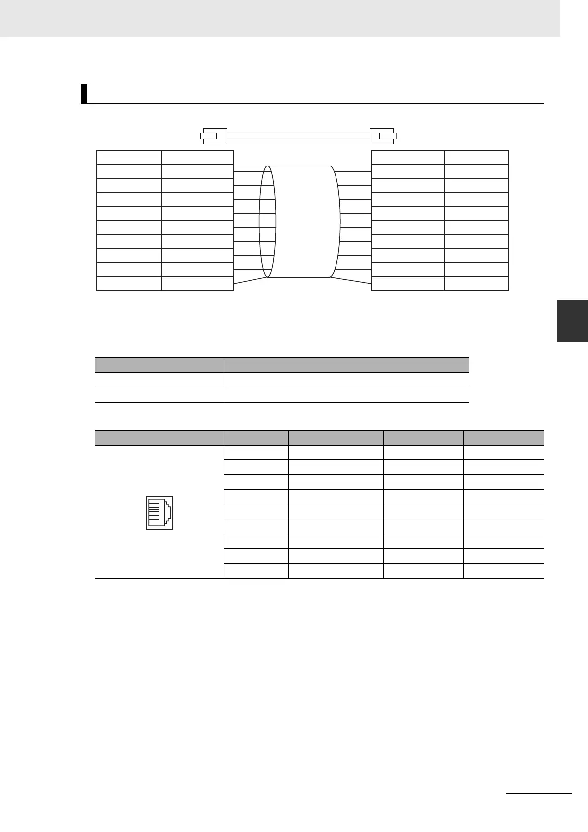
Use straight wiring to attach the connectors to the communications cable.
*1 Connect the cable shield to the connector hood at both ends of the cable.
*2 There are two connection methods for Ethernet: T568A and T568B. The T568A connection method is shown
above, but the T568B connection method can also be used.
Connector Specifications
Pin Assignments
Attaching the Connectors to the Cable and Pin Assignments
Specification Description
Electrical characteristics Conforms to IEEE 802.3 standards.
Connector structure RJ45 8-pin modular connector (Conforms to ISO 8877.)
Pin No. Signal name Abbreviation Signal direction
1 Transmission data + TD+ Output
2 Transmission data − TD− Output
3 Reception data + RD+ Input
4 Not used. --- ---
5 Not used. --- ---
6 Reception data − RD− Input
7 Not used. --- ---
8 Not used. --- ---
Hood Frame ground FG ---
1
2
3
4
5
6
7
8
1
2
3
4
5
6
7
8
Shield
Shield
White-BrownWhite-Brown
BlueBlue
White-Orange
White-Orange
Brown Brown
HoodHood
Orange Orange
White-Blue White-Blue
Green
Green
Wire colorWire color
White-Green White-Green
Pin No. Pin No.

 Loading...


