4-9
4 EtherCAT Network Wiring
NJ/NX-series CPU Unit Built-in EtherCAT Port User’s Manual (W505)
4-1 Laying the EtherCAT Network
4
4-1-5 Cable Connection Procedure
Precautions for Correct UsePrecautions for Correct Use
• Turn OFF the Controller’s power supply before connecting or disconnecting Ethernet commu-
nications cable.
• Allow extra space for the bending radius of the communications cable. The required space
depends on the communications cable, connector, and CPU Unit that are used.
Refer to the NJ-series CPU Unit Hardware User’s Manual (Cat. No. W500) for details on the
NJ-series CPU Unit.
Refer to the NX-series CPU Unit Hardware User’s Manual (Cat. No. W535) for details on the
NX701 CPU Unit.
Refer to the NX-series NX102 CPU Unit Hardware User’s Manual (Cat. No. W593) for details
on the NX102 CPU Unit.
Refer to the NX-series NX1P2 CPU Unit Hardware User’s Manual (Cat. No. W578) for details
on the NX1P2 CPU Unit.
1
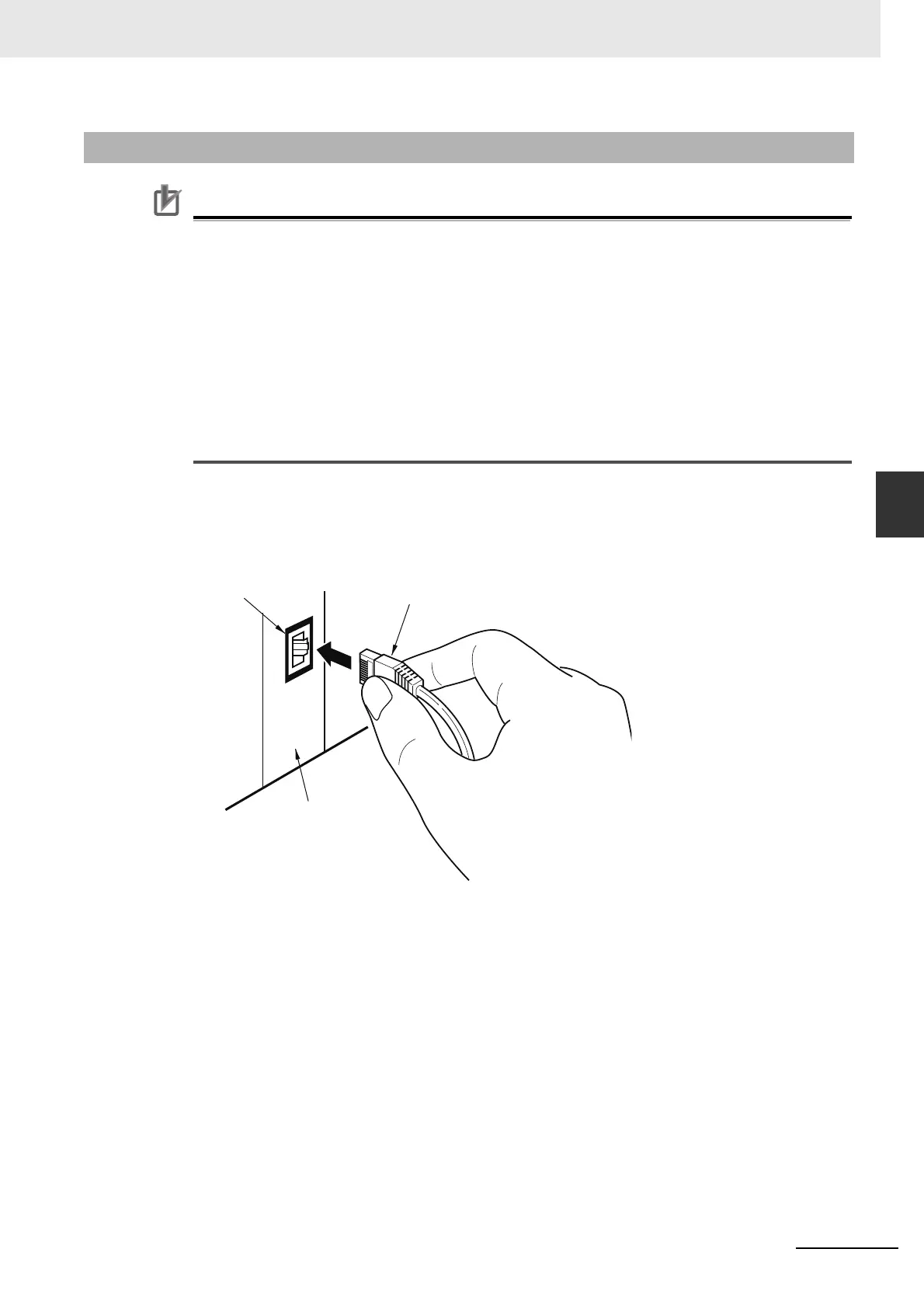
Lay the Ethernet communications cable.
2
Connect the Ethernet communications cable to the built-in EtherCAT port on the NJ/NX-series
CPU Unit. Firmly insert the connector until it locks into place.
4-1-5 Cable Connection Procedure
CPU Unit
RJ45 Modular Connector
Built-in EtherCAT port

 Loading...


