SeHing
the
Needle
Threader
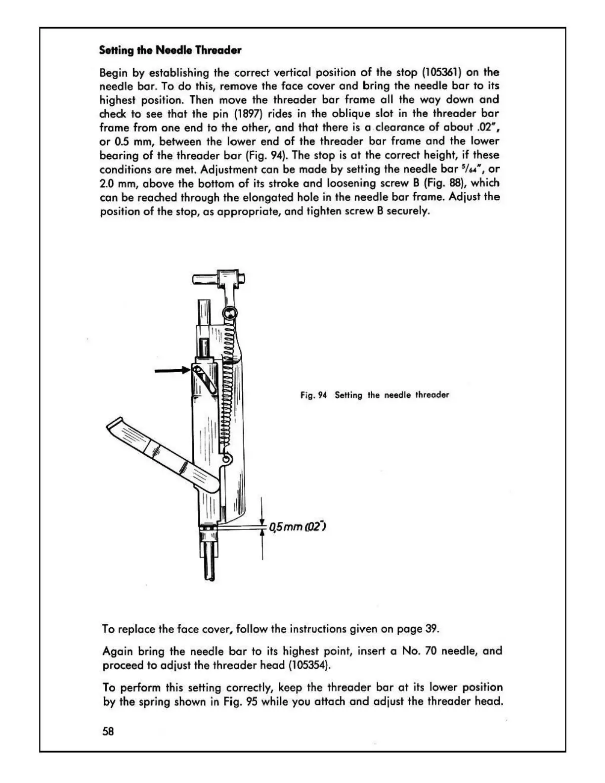
Begin by establishing the correct vertical position
of
the stop
(105361)
on the
needle bar.
To
do
this, remove the face cover
and
bring the needle
bar
to its
highest position. Then move the threader
bar
frame all the way down
and
check to see that the pin
(1897)
rides
in
the oblique slot
in
the threader
bar
frame from one end
to
the other,
and
that there
is
a clearance
of
about
.02
..
,
or
0.5
mm,
between the lower end
of
the threader
bar
frame
and
the lower
bearing
of
the threader
bar
(Fig
.
94)
. The stop
is
at
the correct height,
if
these
conditions
ore
met. Adjustment con be mode by setting the needle
bars
;
,~
..
,
or
2.0
mm,
above
the bottom
of
its stroke and loosening screw B
(Fig.
88)
, which
con be reached through the elongated hole
in
the needle
bar
frame. Adjust the
position of the stop,
as
appropr
iate, and tighten screw B securely.
Fig.
94
Setting the needle threoder
To
replace the face cover, follow the instructions given on
page
39.
Again bring the needle
bar
to
its highest point, insert o No.
70
needle,
and
proceed
to
adjust the threader head
(105354
).
To
perform this setting c:orrectly
1
keep the threader
bar
at
its
lower position
by the spring shown
in
Fig.
95
while you attach
and
adjust the threader head.
58

 Loading...