PG DRIVES TECHNOLOGY S-DRIVE - INSTALLATION
SK76745/10
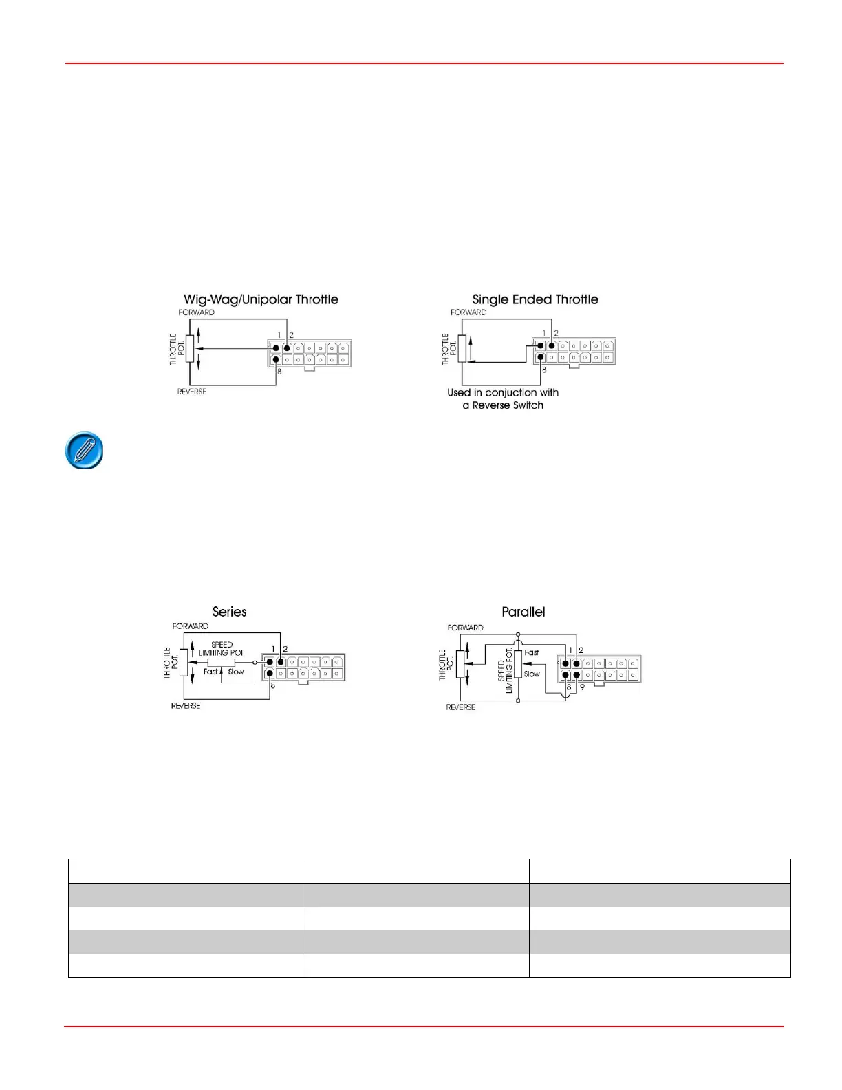
4.1 Throttle Potentiometer Configuration
Pins 1,2 and 8 are the connections to the throttle potentiometer. Wig-wag, Single-ended and Unipolar throttle configurations can
be used but you should ensure the controller is programmed to the correct type. Refer to Chapter 3.
The value of the potentiometer should be 5k ± 20%. If the full electrical span of the potentiometer is not used, Throttle Gain
can be programmed such that full speed can be achieved. Refer to the chapter 3.
If the scooter has a wig-wag throttle configuration it is possible, by programming, to reverse the polarity of operation of the
throttle. For single ended throttles the polarity of operation of the reverse switch can be selected. Refer to Chapter 3.
For compliance with ISO7176-14: 2008, the throttle wiring recommendations in Appendix A (Annex – S-Drive command signal
leakage) should be followed.
Other factory programmed throttle inputs are available such as a voltage input that accepts
signals in the range of 0-5V. Please contact PGDT for details.
4.2 Speed Limiting Potentiometer Configuration
A speed limiting potentiometer may be connected in two ways.
In series with the throttle potentiometer wiper.
In parallel with the throttle potentiometer, through pin 9.
The illustration shows both connection variants with a wig-wag throttle.
If a series type connection is made a value of 25K will result in the scooter driving at 30% of maximum speed.
If a parallel type connection is made a potentiometer of 100K value should be used. The potentiometer should be connected
so its wiper is connected to the throttle high reference when the potentiometer is in the fast position. The effect of the
potentiometer is explained in the table below.
When a parallel type connection is made the S-Drive requires to be programmed as follows.
 Loading...
