PG DRIVES TECHNOLOGY S-DRIVE - INSTALLATION
SK76745/10
6 Charger/Programming Connections (Off-board & On-board)
The controller has been designed to allow both Charging and Programming through the Molex 4-way connector. This connector
can be used either directly or via a Neutrik NC3MX socket.
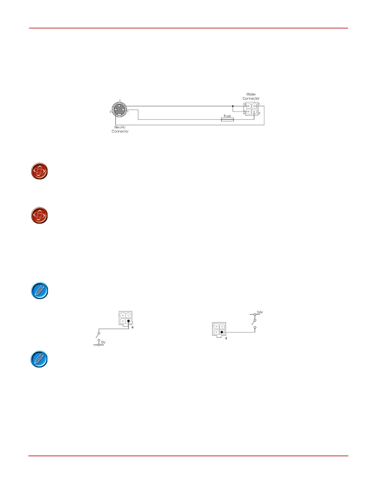
In order to use a Neutrik socket the charger/programming loom should be wired as below.
For both Off-board and On-board Charging, the maximum charging current is 9A rms. Refer to Section 3 of this chapter for pin-
out details of this connector.
Do not exceed the maximum charging current of 9 A rms. Always use the PGDT specified charger
connectors. Failure to observe these conditions could result in poor contact resistance in the
charger connector resulting in overheating of the charger plugs. This presents a potential burn
hazard for the user. PGDT accepts no liability for losses of any kind arising from failure to
comply with this condition. Ensure that the charger plug pins are of the correct type.
The scooter manufacturer must install a suitable fuse to protect the scooter’s wiring. PGDT recommends
that the fuse is fitted as close as possible to the 4-way Molex connector. Failure to comply with this
could result in a fire hazard. PGDT accepts no liability for losses of any kind arising from failure to
comply with this condition.
6.1 Inhibit 1
The S-Drive Scooter Controller has 3 highly versatile inputs that can be configured to provide inhibit and speed limiting functions.
These inputs are referred to as Inhibit 1, Inhibit 2 and Inhibit 3. Inhibit 1 input is located on the 4 way charger connector.
If this Inhibit is not to be used PGDT recommends that the Inhibit Speed parameter be set to
100%.
It is possible to connect the switch to 24V or 0V.
Inhibit 1 is programmed primarily to detect a charger inhibit condition, such as an off board charger being connected to the
scooter or an onboard charger being connected to the line.
See the example in section 6.1.3
Inhibit 1 input has 3 programmable parameters.
Inhibit 1 Mode
Inhibit 1 Speed
Inhibit 1 Operation
 Loading...
