PG DRIVES TECHNOLOGY S-DRIVE - INSTALLATION
SK76745/10
Latched - Means the inhibitor, such as the charger plug, must be removed and the controller turned off and
on before the scooter can be operated again.
Non-Latched - Means the controller can be reset to an operational state by removing the inhibitor.
If set to Latched, then when Inhibit 3 is active the TruCharge display will step-up to indicate the scooter is charging.
Example - To provide a charge inhibit function that is active when Inhibit 3 is connected to 0V and is latching, program as below.
Mode = 1
Speed Limit Value = 0
Operation = Latched
If this Inhibit is activated then the controller will cause the scooter to decelerate to a complete stop (as if the throttle has been
released).
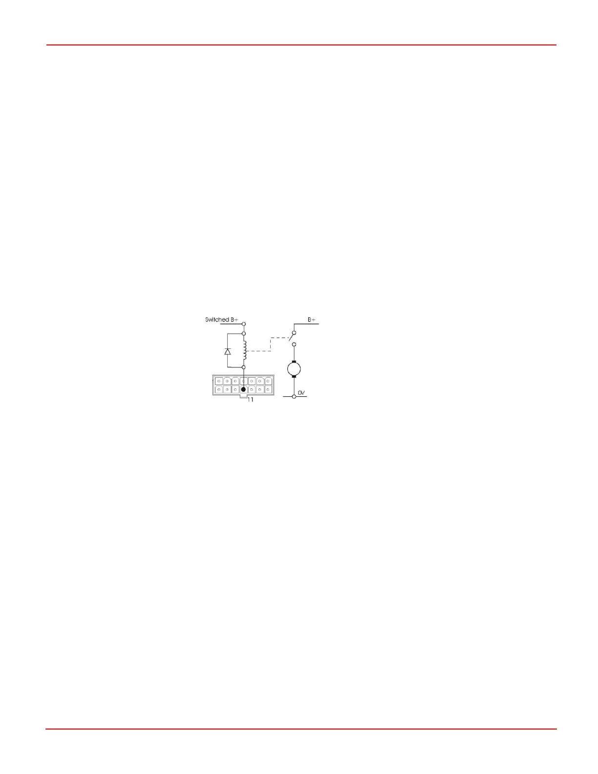
4.13 Auxiliary Output
Pin 11 is a 1A self-protected output, which can be programmed to operate an external relay. The parameter that must be
programmed is aux output mode. Refer to chapter 3 for programming details.
5 Drive Motors
The controller is designed to be connected to a permanent magnet DC motor, fitted with suitable gearbox and solenoid brake.
In order to optimize the performance of the scooter, the controller must be matched to the motor terminal impedance. This
matching is implemented by programming the controller. The parameter for adjustment is Motor Compensation. Refer to
Chapter 3.
The Motor Compensation value should be set in accordance with the armature resistance of the motor and all cables and
connectors between the S-Drive and the motor. The value is set in milli-Ohms (mOhms). A recommended value is:
60% of the (armature resistance + cables and connectors)
Motor manufacturers should be able to supply figures for armature resistance and cable and connectors may typically be
40mOhms.
Example:
Motor has armature resistance of 200mOhms
Cables and connectors are 40mOhms
Set Motor Compensation to 0.6 x (200 + 40) = 145mOhms
Failure to match the controller with the motors may result in poor control characteristics.
 Loading...
