S-DRIVE - INSTALLATION PG DRIVES TECHNOLOGY
SK76745/10
4.11 Inhibit 2
The S-Drive Scooter Controller has 3 highly versatile inputs that can be configured to provide inhibit and speed limiting functions.
These inputs are referred to as Inhibit 1, Inhibit 2 and Inhibit 3. Inhibit 2 input is located at pin 6 of the 14 way tiller connector.
If this Inhibit is not to be used PGDT recommends that the Inhibit Speed parameter be set to
100%.
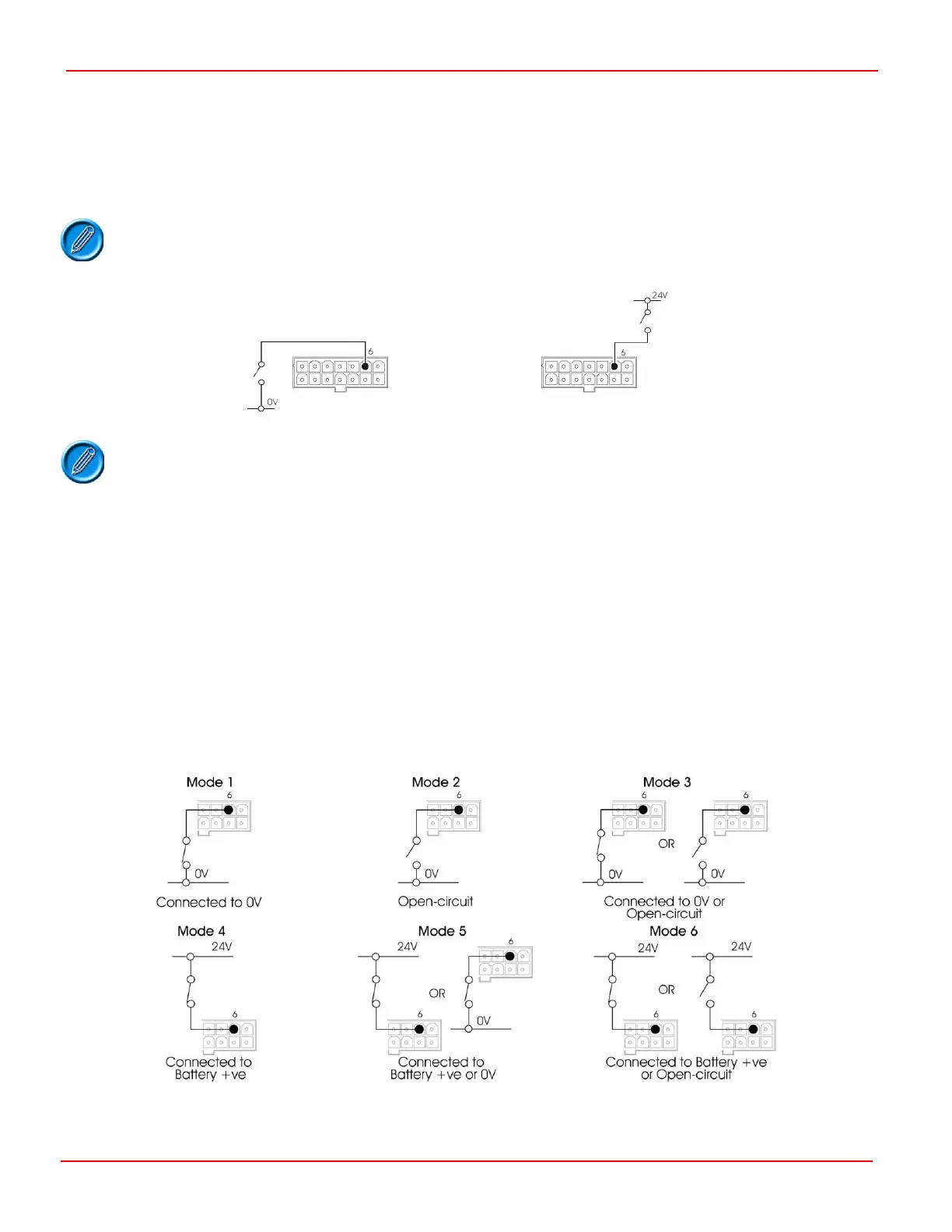
It is possible to connect the switch to 24V or 0V.
Inhibit 2 is intended primarily to detect the presence of external devices such as height switches or brake release switches. These
can be used to either limit the maximum speed of the scooter or stop it completely.
See the example in section 4.11.3
Inhibit 2 input has 3 programmable parameters.
Inhibit 2 Mode
Inhibit 2 Speed
Inhibit 2 Operation
4.11.1 Inhibit 2 Mode
The Mode parameter refers to the state in which the inhibit is active.
 Loading...
