Home
Polaris
Offroad Vehicle
A12MH46AX
Polaris A12MH46AX User Manual
4
of 1
of 1 rating
432 pages
Give review
Manual
Specs
To Next Page
To Next Page
To Previous Page
To Previous Page
Loading...
8.3
TRANSMISSION
8
9923412 - 2012 Sportsman 400/50
0 and EFI Tractor Service Manua
l
© Copyright 201
1 Polaris Sales Inc.
T
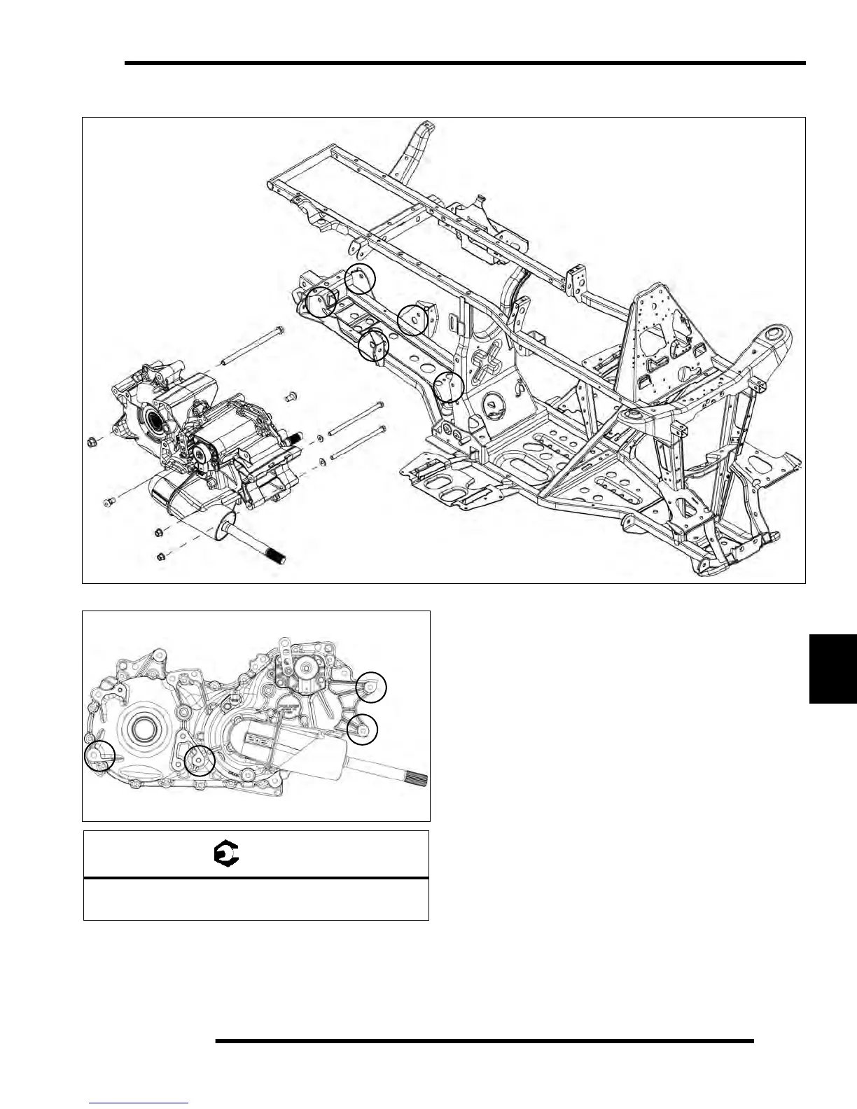
ransmission Frame Mounts
T
ransmission Fra
me Mount Locations
A
A
A
B
B
=
T
A = Frame Long Bolts = 37 ft. lbs / 50Nm
B = Side Fasteners = 37
ft. lbs / 50Nm
308
310
Table of Contents
General Information Chapter 1 1
4
General
4
Table of Contents
4
Chapter 1 Model Number
5
General Information
5
Model Number Information
5
Vehicle Identification Number (Vin)1.2
5
Engine Designation Numbers
5
Vehicle and Engine Serial Numbers
5
Transmission I.D. Location
6
Publication Part Numbers
6
Maintenance
7
Vehicle Specifications
7
2012 Sportsman 400 H.o
7
2012 Sportsman 500 H.o
9
2012 Sportsman Touring 500 Ho
11
2012 Sportsman Forest Tractor 500 Efi
13
Misc. Numbers/Charts
15
Conversion Table
15
Standard Bolt Torque Specification
16
Metric Bolt Torque Specification
16
Metric Tap Drill Sizes
17
Paint Codes
18
Replacement Keys
18
Glossary of Terms
19
Maintenance Chapter 2 Maintenance 2
20
Maintenance
23
Chapter 2 Periodic Maintenance Chart
25
Lubricants / Service Products
26
Polaris Lubricants, Maintenance and Service Products
26
Lubrication / Fluids
26
Pre-Ride / Daily Inspection
26
Lubrication Components
27
Front Gearcase Lubrication
28
Transmission Lubrication
29
Adc System (if Equipped)
30
Adc System Fluid Reservoir Location
30
Adc Differential Hydraulic Circuit Fluid Change
30
Vehicle Inspection
31
Shift Link Rod Inspection
31
Throttle Inspection
31
Throttle Cable / Electronic Throttle Control Adjustment
32
Fuel System
32
Fuel Lines
33
Vent Lines
33
Choke (Enricher) Adjustment - (500 Carb)
33
Compression Test
33
Engine Mounts
33
Spark Plug
34
Battery Maintenance
34
Liquid Cooling System Overview
35
Coolant Strength / Type
35
Cooling System Hoses
35
Radiator/Grill Screen
36
Cooling System Pressure Test
36
Coolant Level Inspection
36
Radiator Coolant Level
37
Air Filter/Pre-Filter Service
38
Air Box Sediment Tube
39
Breather Filter Inspection
39
Breather Hose
39
Recoil Housing
39
Engine Oil Level
40
Oil and Filter Change
40
Oil Pump Priming Procedure
42
Valve Clearance
42
Intake Valve Clearance Adjustment
43
Exhaust Valve Clearance Adjustment
43
Steering
43
Final Drive
44
Tie Rod End/Steering Inspection
44
Camber and Caster
44
Wheel Alignment
44
Toe Alignment Adjustment
45
Exhaust Pipe
45
Brake System Inspection
46
Brake Pad Inspection
47
Hose/Fitting Inspection
47
Auxiliary Brake Testing
47
Auxiliary Brake Adjustment (Hydraulic)
48
Suspension Spring
48
Preload Adjustment
48
Front Suspension
48
CV Shaft Boot Inspection
48
Controls
49
Wheels
49
Wheel, Hub, and Spindle
49
Torque Table2.30
49
Wheel Removal Front or Rear
50
Wheel Installation
50
Tire Pressure
50
Tire Inspection
51
Frame, Nuts, Bolts, Fasteners
51
Carburetor Maintenance
51
Choke (Enricher) Adjustment (Non Efi)
51
Pilot Screw
51
Pilot Screw Adjustment
52
Idle Speed Adjustment (Non Efi)
53
Fuel Filter (Non Efi)
53
Carburetor Draining
54
Maintenance Schedule
55
Chapter 3 Engine
56
Engine Fastener Torque Patterns
58
Specifications
58
Torque Specifications
58
Sportsman 500 H.o. Engine Service Data
59
Sportsman 400 H.o. Engine Service Data
61
General Engine Service
63
Cooling System Specifications
63
Cooling System
64
Accessible Components
65
Engine Removal
65
Engine Installation Notes
67
Cylinder Hone Selection/ Honing Procedure
67
Electrical
68
Honing to Oversize
68
Cleaning the Cylinder after Honing
68
Crankshaft Straightening
69
Engine Lubrication
69
Oil Pressure Test
69
Oil Flow
70
Oil Flow Diagram
71
Engine Exploded Views
72
Special Tools
63
Engine Disassembly
73
Cam Chain Tensioner / Rocker Arm /Camshaft Removal
73
Cam Chain Tensioner Inspection
73
Rocker Arm / Shaft Inspection
74
Camshaft Removal
75
Automatic Compression Release Removal / Inspection
76
Automatic Compression Release Installation
76
Camshaft Inspection
77
Cylinder Head Removal
77
Cylinder Head Exploded View
78
Cylinder Head Inspection
79
Cylinder Head Warpage
79
Cylinder Head Disassembly
79
Valve Inspection
80
Combustion Chamber
81
Valve Seat Reconditioning
81
Cylinder Head Assembly
84
Valve Sealing Test
84
Valve Clearance Adjustment
84
Cylinder / Piston Removal and Inspection
85
Piston Removal
86
Cylinder Inspection
87
Cylinder Hone Selection / Honing Procedure
87
Honing to Oversize
88
Cleaning the Cylinder after Honing
88
Piston-To-Cylinder Clearance
89
Piston / Rod Inspection
89
Piston Identification
90
Piston Ring Installed Gap
90
Crankcase Disassembly
91
Starter Drive Removal / Inspection
91
Flywheel and Stator Removal / Inspection
91
Cam Chain / Tensioner Blade
92
One Way Valve
93
Crankcase Separation
93
Oil Pump Removal / Inspection
93
Oil Pump Assembly
95
Counter Balancer Shaft Removal / Inspection
95
Crankshaft Removal / Inspection
96
Crankcase Bearing Inspection
97
Oil Seal / Mechanical Seal Removal (Engine Disassembled)
97
Crankcase Inspection
97
Bearing Installation
98
End Play Inspection / Adjustment
98
Crankshaft End Play Adjustment
98
Counter Balancer Shaft End Play Adjustment
99
Oil Pump Shaft End Play Adjustment
100
Engine Reassembly
100
Pump Shaft Oil Seal Installation
100
Crankshaft / Counter Balance / Oil Pump Installation
100
Crankcase Assembly
101
Water Pump Mechanical Seal Installation
101
Water Pump Mechanical Seal Removal (Engine Installed)
102
One Way Valve Installation
103
Cam Chain Drive Sprocket Installation
103
Tensioner Blade Installation
103
Piston Ring Installation
103
Piston Installation
104
Cylinder Installation
104
Cylinder Head Installation
105
Cam Chain / Camshaft Installation
106
Camshaft Timing
106
Camshaft Timing Illustration
108
Cam Chain Tensioner Installation
109
Stator, Flywheel and Starter Drive Installation
109
Rocker Shaft / Rocker Arm Assembly Installation
110
Thermostat Installation
110
Oil Pipes
110
Oil Pump Priming Procedure
110
Recoil (Accessory)
111
Troubleshooting
113
Carburation and Fuel System Chapter 4 Carburation and Fuel System
118
Carburetor Jetting
119
Chapter 4
119
General Information and Specifications
119
Mikuni Jet Part Numbers
119
Special Tools
119
Carburetion
120
Bst 40 Carburetor Exploded View 1 of 2
120
Bst 40 Carburetor Exploded View 2 of 2
121
CV Carburetor System Function
122
Mikuni CV Carb Operation
122
Carburetor Venting
123
Starter System (Choke or Enrichment)
123
Pilot (Idle and Slow) System
124
Main System
124
Float System
125
Pilot Screw
125
Air/Fuel Mixture Ratio
126
Jet Needle
126
Needle Jet
126
Throttle Opening Vs. Fuel Flow
127
Carburetor Disassembly - Mikuni CV
127
Carburetor Cleaning
128
Carburetor Inspection
128
Carburetor Assembly
129
Float Height Adjustment
129
Needle and Seat Leakage Test
130
Fuel Level Test
130
Carbutated Fuel Tank / Fuel Delivery System
131
Fuel Gauge Sending Unit Test
132
Fuel Pump (Carburated)
132
Fuel Pick-Up / Sending Unit Replacement (Carb.)
133
Fuel Tank Vent Routing (Non Intl)
136
500 H.o. International Emissions System
137
Troubleshooting
138
Carburation and Fuel System Notes
140
Special Tools
142
500 Efi Tractor Speed Control
144
System Operation Overview
144
Air Control Body Removal and Disassembly
145
Air Control Body Assembly and Installation
145
Air Solenoid Valve Test / Replacement
145
Exhaust System
146
Efi Service Notes
147
Efi System Exploded View
148
Efi System
149
Component Locations/Identification
149
Fuel System and Fuel Tank
151
Fuel System and Fuel Tank Exploded View
151
Electronic Fuel Injection
152
General Information
152
Efi Operation Overview
152
Initial Priming / Starting Procedure
152
Electronic Control Unit (Ecu)
153
Operation Overview
153
Ecu Replacement
154
Ecu Service
154
Fuel Lines
153
Quick Connect Removal/Installation
153
Fuel Pump Assembly
155
Operation / Testing
155
Fuel Pump Test
155
Fuel Tank Replacement
156
Fuel Sending Unit Test
157
Fuel Pump Replacement
158
Fuel Filter
161
Fuel Injector
161
Fuel Pressure Regulator
161
Crankshaft Position Sensor (Cps)
163
Manifold Air Pressure Sensor (Map)
164
Operation Overview
164
Map Sensor Test
164
Map Sensor Replacement
164
Idle Air Control (Iac)
165
Intake Air Temperature Sensor (Iat)
165
Operation Overview
165
Intake Air Temperature Sensor Test
165
Intake Air Temperature Sensor Replacement
165
Throttle Position Sensor (Tps)
166
Operation Overview
166
Throttle Position Sensor Test
166
Throttle Position Sensor Replacement
168
Throttle Position Sensor Initialization
168
Engine Temperature Sensor
169
General Information
169
Engine Temperature Sensor Test
169
Engine Temperature Sensor Replacement
169
Fuel System Troubleshooting
170
Fuel Starvation / Lean Mixture
170
Efi Diagnostics Using 'Blink Codes
171
Blink Codes - Operation
171
Digital Wrench™ Operation
172
Digital Wrench™ Diagnostic Software Overview
172
Special Tools (also Refer to Page 3.2)
172
Diagnostic Software Version
172
Ecu Replacement
172
Guided Diagnostic Available
172
Digital Wrench™ Communication Errors
173
Digital Wrench™ - Diagnostic Connector
173
Digital Wrench™ Version and Update ID
174
Digital Wrench™ Updates
174
Digital Wrench™ Serial Number Location
175
Digital Wrench™ Feature Map
176
Engine Controller Reprogramming (Reflash)
177
Troubleshooting Diagrams
180
Efi Circuit - Power on
180
Efi Circuit - Crank Position Sensor
180
Efi Circuit - Fuel Pump
181
Efi Circuit - Ignition Coil
181
Efi Circuit - Idle Air Control
182
Efi Circuit - Throttle Position Sensor
182
Efi Circuit - Manifold Absolute Pressure Sensor
183
Efi Circuit - Engine Coolant Temperature
183
Efi Circuit - Air Temperature Sensor
184
Efi Circuit - Malfunction Indicator Light
184
Body / Steering / Suspension Chapter 5 Body / Steering / Suspension
186
Chapter 5
187
Decal Replacement
187
General Information
187
Special Tools
187
Torque Specifications
187
Plastic Insert Removal / Installation
188
Body
189
Side Panel Removal
189
Foot Well Removal / Installation
190
Front Bumper Removal / Installation
191
Mud Guard Removal / Installation
191
Front Fender Removal/Installation
192
Front Rack / Storage Box Lid Assembly
193
Front Cab Assembly
194
Front Bumper Assembly
195
Rear Rack Assembly
196
Rear Cab and Seat Assembly
197
Rear Storage Box Assembly
198
Winch and Front Bumper Mounting
199
Headlight Pod Exploded View
200
500 Efi Tractor Seat Assembly
201
Overview
201
Seat Dampener Repair
201
Seat Pivot Repair
201
500 EFI Tractor Seat Assembly Exploded View
202
500 Efi Tractor Steering Post and Lock
203
Steering Assembly Exploded View
203
Steering
204
Handlebar Block Installation Procedure
204
Steering / A-Arm Exploded View
205
A-Arm Replacement
206
Ball Joint Replacement
207
Steering Post Removal
208
Steering Post Assembly
208
Suspension
208
Front Strut Cartridge Replacement
208
Strut Assembly
209
Sportsman Rear Suspension Assembly
210
Torsion Bar Exploded View
211
Chapter 6 Clutching
213
General Operation
214
Pvt System Overview
214
Special Tool and Supplies
214
Torque Specifications
214
Drive Clutch Operation
215
Driven Clutch Operation
215
Clutching Chart
216
Maintenance / Inspection
216
Pvt Break-In (Drive Belt / Clutches)
216
Overheating / Diagnosis
217
Pvt Exploded Views
218
Pvt System Service
219
Disassembly
219
Assembly
220
Drive Belt
221
Belt Removal
221
Belt Inspection
222
Belt Installation
222
Pvt Break-In (Drive Belt / Clutches)
222
Clutch Alignment
222
Clutch Center Distance
224
Drive Clutch Service (Non Ebs)
225
Exploded View (Non Ebs)
225
Clutch Disassembly
226
Drive Clutch Spring Inspection
227
Shift Weight Inspection
227
Spider Removal
228
Button to Tower Clearance Inspection
229
Shift Weight Inspection
229
Bearing Inspection
230
Clutch Inspection
230
Moveable Sheave Bushing Inspection
231
Clutch Assembly
232
Ebs Drive Clutch Service
233
Ebs Drive Clutch Exploded View
233
Drive Clutch Disassembly
233
Spider Removal
234
Button to Tower Clearance Inspection
235
Shift Weight Inspection
235
Drive Clutch Inspection
236
Moveable Sheave Bushing Inspection
237
One-Way Clutch Inspection (Ebs Drive Clutch)
237
Drive Clutch Reassembly
238
Drive Clutch Bushing Service (Non Ebs and Ebs)
239
Non Ebs Driven Clutch
242
Driven Clutch Service (Ebs)
247
Driven Clutch Bushing Service
254
Troubleshooting
256
Chapter 7 Final Drive
259
Gearcase Fluid / Capacity
260
Special Tools
260
Specifications
260
Torque Table
260
Front Hub
261
Disassembly
261
Assembly
261
Front Gearcase Removal and Installiation (Adc and Non Adc)
262
Gearcase Removal
262
Gearcase Installation
263
Front Gearcase - Centralized Hilliard Non Adc (4X4)
264
Operation Non Adc
266
Disassembly / Inspection Non Adc
267
Reassembly / Inspection Non Adc
270
Front Gearcase Diagnosis
272
Setting Ring Gear Backlash Non Adc
274
Front Gearcase - Centralized Hilliard Adc
275
Operation
275
Adc Gearcase Exploded View
276
Adc Operation
277
Front Gearcase Diagnosis
278
Coil Testing
279
Adc Differential Hydraulic Circuit Bleeding
279
Disassembly / Inspection
280
Adc Gearcase Piston Replacement Procedure
284
Assembly
285
Setting Ring Gear Backlash
288
Front Drive (CV) Shaft
289
Inspection
289
Removal
289
Installation
291
Rear Hub
292
Removal
292
Disassembly
293
Assembly
294
Installation
294
Rear Drive (CV) Shaft
295
Inspection
295
Removal
295
Installation
296
CV Drive Shaft Service
297
Drive Shafts and Propshafts Components
297
Drive Shaft and CV Joint Handling Tips
298
Outer CV Joint / Boot Replacement
298
Inner Plunging Joint / Boot Replacement
301
Drive Shaft Exploded Views
304
Prop Shaft - Front or Rear
304
Removal and Installation
304
U-Joint Service
305
Disassembly
305
Assembly
306
Transmission Chapter 8 Transmission
307
Chapter 8
308
Lubrication
308
Special Tools
308
Torque Specifications
308
Transmission - General
308
Transmission Frame Mounts
309
Transmission Upper Frame Mount
310
Transmission Rear Stabilizer Mounts
311
Transmission Control Arm Bracket Mounts
312
Gear Selector Removal
313
Shift Linkage Inspection
313
Transmission Removal
313
Transmission Installation
314
Troubleshooting Checklist
314
2012 Sportsman Transmission Exploded View
315
Transmission Disassembly / Assembly
317
Transmission Disassembly
317
Snorkel / Output Gear Backlash Procedure
322
Transmission Assembly
325
Brakes Chapter 9 Brakes
331
Chapter 9
332
Component Service Limits
332
Specifications
332
Torque Table
332
Hydraulic Brake System
333
Operation Overview
333
Overview: Sportsman Forest 500 (Intl A12Mh50Ff)
334
Brake Noise Troubleshooting
334
Brake Bleeding / Fluid Change
335
Special Tools
333
Brake System Exploded Views
337
Sportsman Touring 500 Ho Component Exploded View
337
Brake Caliper Exploded Views
340
Sportsman 500 Ho Touring Rear Caliper Assembly (Non Intl.)
340
Sportsman Forest 500 (Intl.) Front Caliper Assembly
341
Front Master Cylinder All Models
342
Removal
342
Installation
342
Front Brakes
343
Pad Removal
343
Assembly
344
Brake Burnishing Procedure
345
Front Brake Disc
345
Front Caliper
347
Removal
347
Inspection
348
Reassembly
348
Installation
349
Rear Brake Pad
350
Touring Pad Removal
350
Touring Pad Installation
351
Sportsman Rear Pad Removal
352
Sportsman Rear Pad Installation
353
Brake Burnishing Procedure
353
Touring Rear Caliper
354
Removal
354
Inspection
355
Reassembly
355
Sportsman Rear Caliper
356
Removal and Inspection
356
Assembly
357
Rear Brake Disc
359
Rear Master Cylinder
360
Sportsman 500 Ho Touring Exploded View (Non Intl)
360
Sportsman 400 Ho, 500 Ho, Tractor 500 (Intl.), Forest 500 (Intl.)
361
Touring Rear Master Cylinder Removal and Installation
362
Sportsman Rear Master Cylinder Removal / Installation
363
Pedal Removal and Installation
364
Troubleshooting
364
Chapter 10 Electrical
365
General Information
367
Ignition System / Basic Electrical Components
367
Special Tools
367
Electrical Service Notes
368
Troubleshooting
368
Instrument Cluster
369
Overview
369
Instrument Cluster Diagnostic Mode
371
Setting a New Service Interval
373
Efi Diagnostic Mode
374
Speedometer Removal
375
Speedometer Installation
375
All Wheel Drive and Speedometer Troubleshooting
376
All Wheel Drive (Awd) Coil
381
Operation Overview
381
Diagnosing System Failures
381
Cooling System Components
381
Fan Control Circuit Operation
381
Fan Control Bypass Test - Efi
381
Fan Control Bypass Test - H.o
381
Fan Motor Current Draw Test
382
Coolant Temperature Sensor - Efi
382
Coolant Temperature Fan Switch - H.o
383
Gear Position Indicator Switch
383
Test Diagram
383
Electronic Throttle Control (Etc) Switch
384
Operation Overview
384
Etc Test
384
Ignition System
385
Overview
385
Components of Alternator and DC / CDI Ignition System
386
Efi Ignition System Testing Flow Chart
387
Crankshaft Position Sensor Gap
387
Ignition Troubleshooting
388
Ignition Output Test Using Gap Tester
388
Charging System
388
Current Draw - Key off
388
Break Even Test
389
Charging System Testing Diagrams
391
Relays
393
Fuses/Circuit Breaker
394
Lighting
394
High Beam Headlight Bulb Replacement
394
Headlight Housing Replacement
395
High Beam Headlight Adjustment
396
Lower Headlamp Removal / Installation
396
Low Beam Headlight Adjustment (Non Intl)
397
Lower Headlight Adjustment (Forest Tractor)
398
Headlamp Switch Test
398
Brake Light Replacement
399
Brake Light Switch
399
Fuel Sender
400
Speed Sensor
400
Accessory Power
401
Starter System
401
Troubleshooting
401
Voltage Drop Test
402
Starter Lockout Troubleshooting- Efi
402
Starter Lockout Troubleshooting- H.o
402
Starter Lockout Diagram- Efi
403
Starter Lockout Diagram- Carb
403
Starter Motor Removal / Disassembly
404
Brush Inspection / Replacement
404
Armature Testing
405
Starter Solenoid Bench Test
406
Starter Exploded View
406
Starter Drive
407
Starter System Testing Flow Chart
408
Battery
409
Battery Identification
409
Battery Conductance Analyzer
409
Battery Activation (Conventional)
410
Battery Terminals/Bolts
410
Conventional Battery Inspection / Removal
411
Conventional Battery Installation
411
Conventional Battery Testing
411
Conventional Battery Ocv - Open Circuit Voltage Test
412
Conventional Battery Specific Gravity Test
412
Battery Load Test
412
Off Season Storage
413
Charging Procedure
413
Low Maintenance Battery
414
Low Maintenance Battery Charging
415
Low Maintenance Battery Inspection / Removal
415
Low Maintenance Battery Installation
415
Low Maintenance Battery - Ocv- Open Circuit Voltage Test
416
Low Maintenance Battery Load Test
416
Low Maintenance Battery Charging Procedure
417
Low Maintenance Battery Off-Season Storage
417
Troubleshooting Diagrams
418
Sportsman 500 Efi Forest Tractor Electrical
420
4
Based on 1 rating
Ask a question
Give review
Questions and Answers:
Need help?
Do you have a question about the Polaris A12MH46AX and is the answer not in the manual?
Ask a question
Polaris A12MH46AX Specifications
General
Brand
Polaris
Model
A12MH46AX
Category
Offroad Vehicle
Language
English
Related product manuals
Polaris ACE 570
152 pages
Polaris ATV 2001
189 pages
Polaris A09BG50AA
256 pages
Polaris ACE 500 2017
174 pages
Polaris ACE 900 2017
512 pages
Polaris ACE 900 2018
512 pages
Polaris ATP 500 4x4 2005
140 pages
Polaris ATP 330 4x4 2005
140 pages
Polaris SPORTSMAN ACE 2014
151 pages
Polaris Axys 800 SWITCHBACK
179 pages
Polaris 600 Switchback Assault
135 pages
325 MAGNUM 4X4 HDS A00CD32FA
59 pages

 Loading...