8
9926813 R04 - 2013-2016 RZR 570 Service Manual
© Copyright Polaris Industries Inc.
8.13
FRONT SUSPENSION
REMOVAL / REPLACEMENT
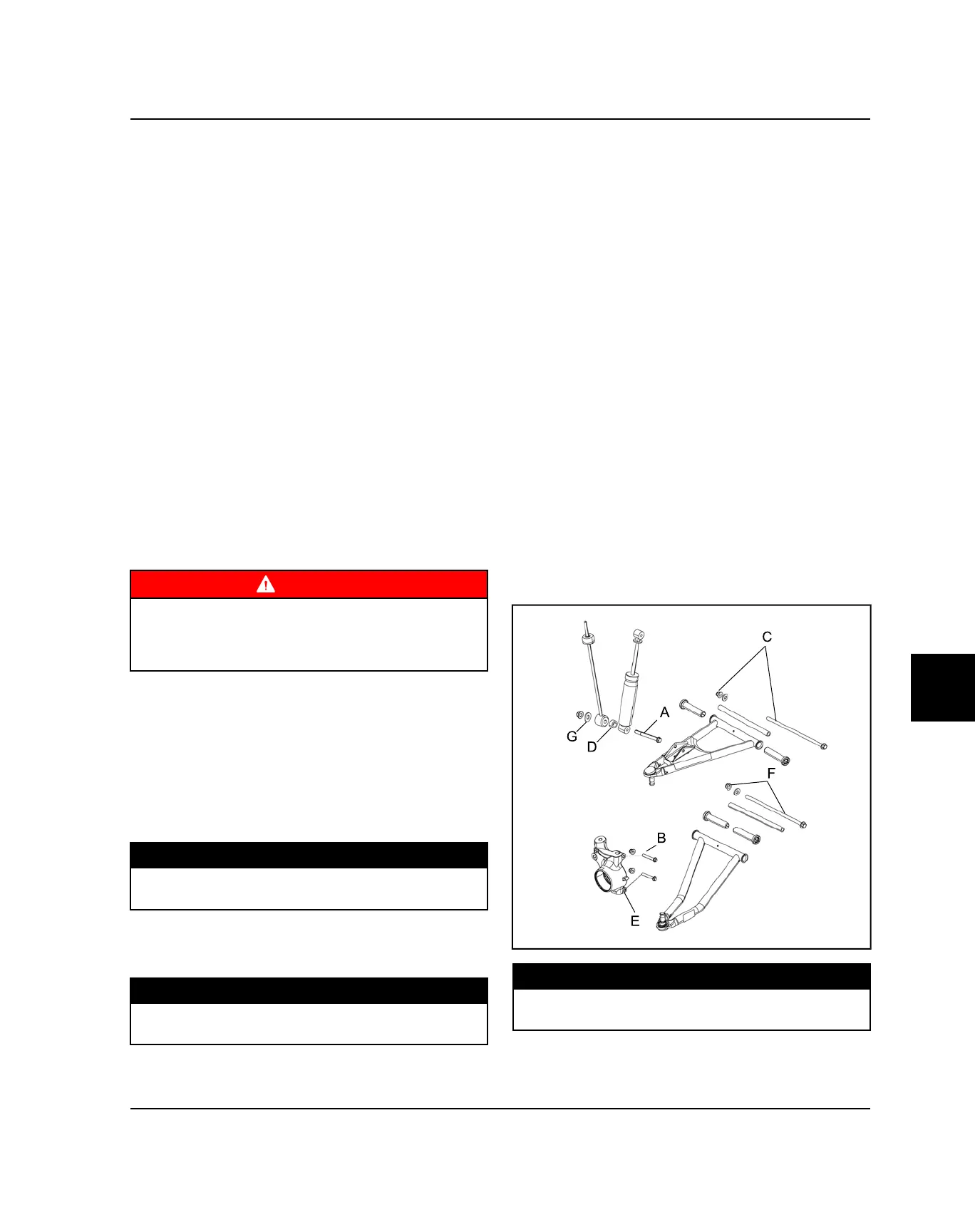
The following procedure details upper and lower A-arm
removal and replacement on one side of the vehicle.
1. Elevate and safely support the front of the vehicle
and remove the front wheel.
2. Remove lower shock fastener (A) from the upper A-
arm.
3. Remove upper ball joint pinch bolt (B) from bearing
carrier.
4. Using a soft face hammer, tap on bearing carrier to
loosen the upper A-arm ball joint end while lifting
upward on the upper A-arm. Completely remove the
ball joint end from the bearing carrier.
5. Remove the front bumper to allow A-arm bolt
removal.
6. Loosen and remove the upper A-arm through-bolt
fastener (C) and remove the upper A-arm from the
vehicle.
7. Examine A-arm bushings and pivot tube (see
“Exploded View”). Replace if worn. Discard
hardware.
WARNING
The locking agent on the existing bolts was destroyed
during removal. DO NOT reuse old hardware. Serious
injury or death could result if fasteners come loose
during operation.
8. If not replacing the A-arm, thoroughly clean the A-
arm and pivot tube.
9. Install new ball joint into A-arm. Refer to “Ball Joint
Replacement” section.
10. Insert new A-arm bushings and pivot tube into new
A-arm.
11. Install new upper A-arm assembly onto vehicle
frame. Torque new bolt to specification.
TORQUE
Front Upper / Lower A-arm Bolts:
39 ft-lb (53 Nm)
12. Insert upper A-arm ball joint end into the bearing
carrier. Install upper ball joint pinch bolt (B) into the
bearing carrier and torque bolt to specification.
TORQUE
Front Ball Joint Pinch Bolts:
23 ft-lb (31 Nm)
13. Attach shock to A-arm with spacer (D) or washer (G)
and fastener (A). Torque lower shock bolt to
specification.
14. Remove lower ball joint pinch bolt (E) from bearing
carrier.
15. Using a soft face hammer, tap on bearing carrier to
loosen the lower A-arm ball joint end while pushing
downward on the lower A-arm. Completely remove
the ball joint end from the bearing carrier.
16. Loosen and remove the lower A-arm through-bolt
fastener (F) and remove the lower A-arm from the
vehicle.
17. Examine A-arm bushings and pivot tube (see
“Exploded View”). Replace if worn. Discard
hardware.
18. If not replacing the A-arm, thoroughly clean the A-
arm and pivot tube.
19. Install new ball joint into A-arm. Refer to “Ball Joint
Replacement” section.
20. Insert new A-arm bushings and pivot tube into new
A-arm.
21. Install new lower A-arm assembly onto vehicle
frame. Torque new bolt to specification.
TORQUE
Front Upper / Lower A-arm Bolts:
39 ft-lb (53 Nm)
STEERING / SUSPENSION
 Loading...