Smart LTE Module Series
Smart EVB G2 User Guide
Smart_EVB_G2_User_Guide Confidential / Released 22 / 59
Inner contact
Outer contact
Figure 9: Power Plug Design
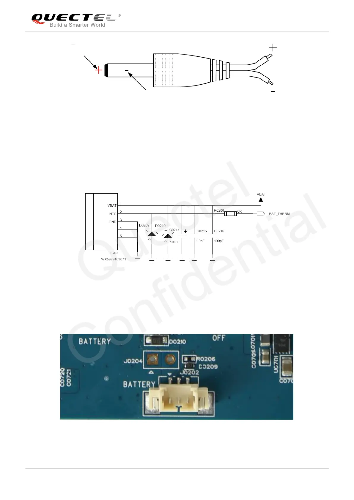
4.1.2. Battery Interface
The following figure shows a reference circuit design for battery interface.
Figure 10: Reference Circuit Design for Battery Interface
The following figure shows the pin assignments of battery interface, and the following table shows the pin
definition of battery interface.
Figure 11: Pin Assignments of Battery Interface
 Loading...