Smart LTE Module Series
Smart EVB G2 User Guide
Smart_EVB_G2_User_Guide Confidential / Released 40 / 59
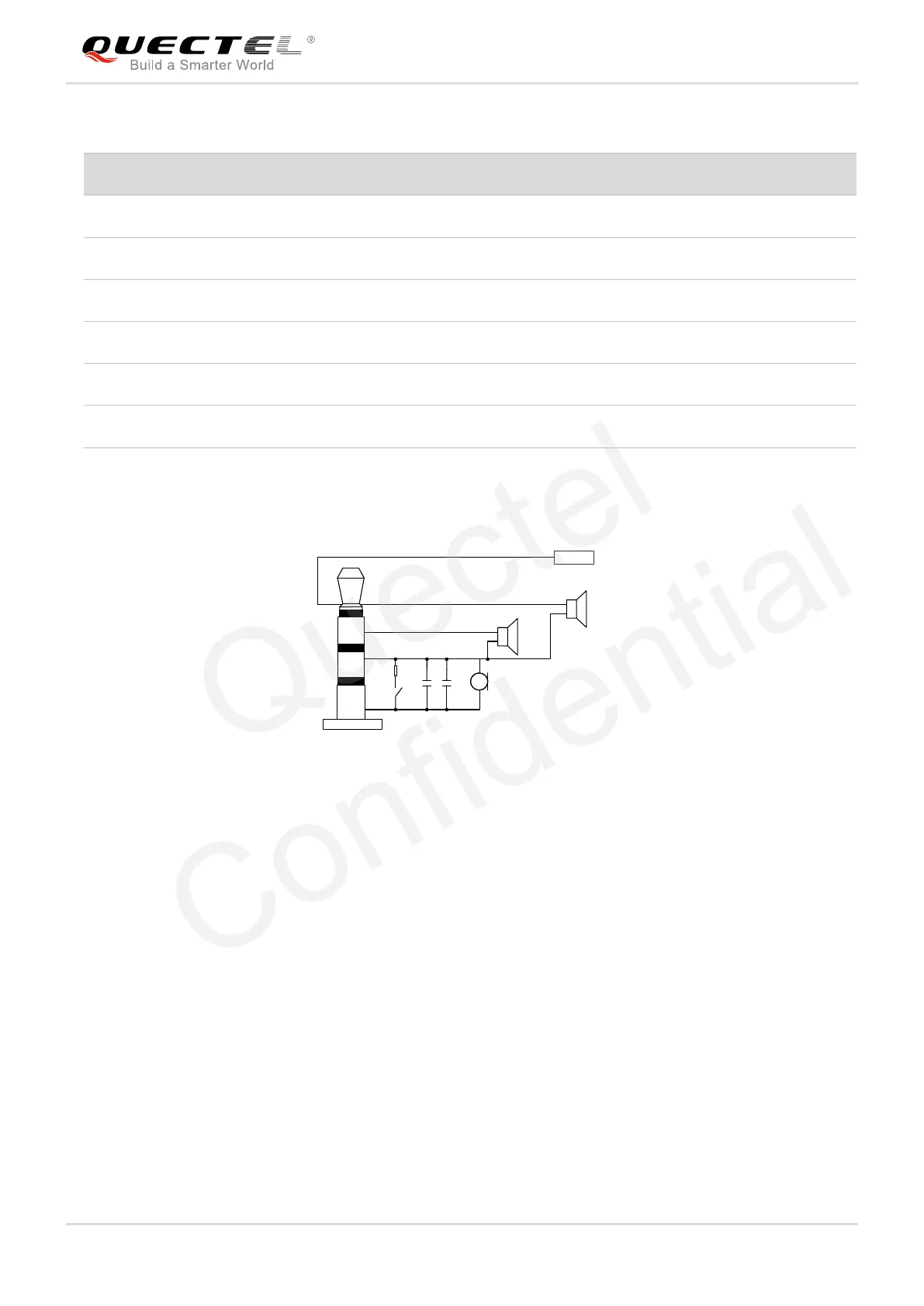
Table 8: Pin Definition of Headset Interface
The following figure shows the sketch design of audio plug which suits for the audio jack on Smart EVB
G2.
2
1
MIC
GND
SW
SPK_R
SPK_L
3
4
32Ω
32Ω
HS_DET
5
Figure 29: Sketch of Audio Plug
4.7.3. Earphone Interface
Smart EVB G2 provides one earphone interface and the earphone is soldered onto the Smart EVB G2 via
test points TP1203 and TP1204. The following figure shows a reference circuit design for earphone
interface.
Positive microphone input
 Loading...