Smart LTE Module Series
Smart EVB G2 User Guide
Smart_EVB_G2_User_Guide Confidential / Released 42 / 59
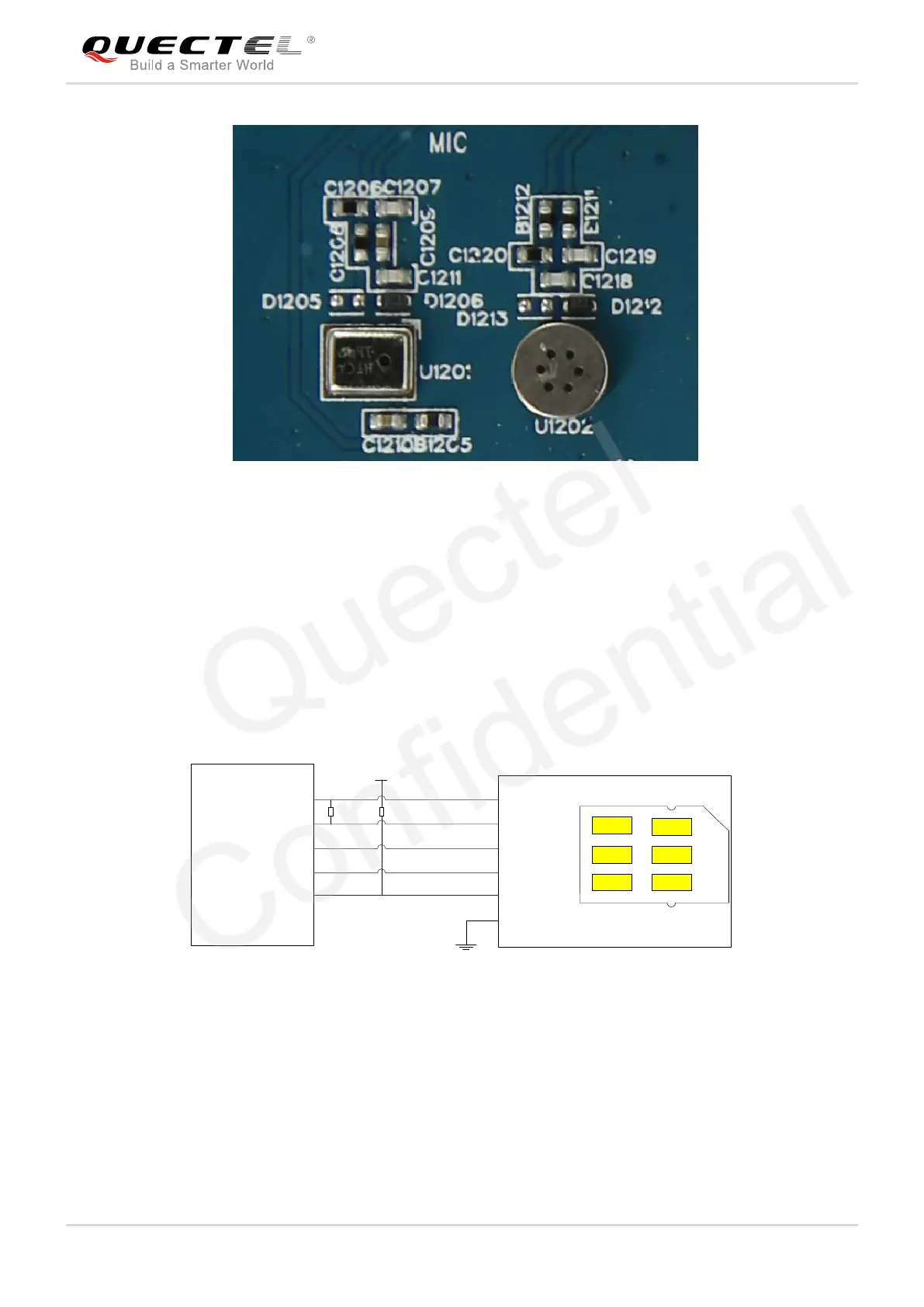
Figure 32: MEMS-Type and ECM-Type Microphones
(U)SIM Interfaces 4.8.
The Smart EVB G2 provides two 6-pin push-push type (U)SIM card (3V or 1.8V) connectors J1001 (main
(U)SIM card connector) and J1002 (Sub (U)SIM card connector). The following figure shows the
simplified interface schematic for J1001.
(U)SIM card connector
USIM
_
VDD
USIM_CLK
USIM
_
DATA
USIM_RST
USIM_GND
Smart-EVB-G2
J1001
C1
C7
C2
C3
Push-Push
USIM_VDD
USIM_
DATA
USIM_
RST
USIM_CLK
USIM
_
PRE
GND
USIM
_
DETECT
CD2
CD1
R1 10K
R2 10K
VDD
Figure 33: Simplified Interface Schematic for (U)SIM Card Connector J1001
The following figure shows the pin assignments of main (U)SIM card connector (J1001).
 Loading...