Raisecom
RC3000E (P100R001) Product Description
Raisecom Proprietary and Confidential
Copyright © Raisecom Technology Co., Ltd.
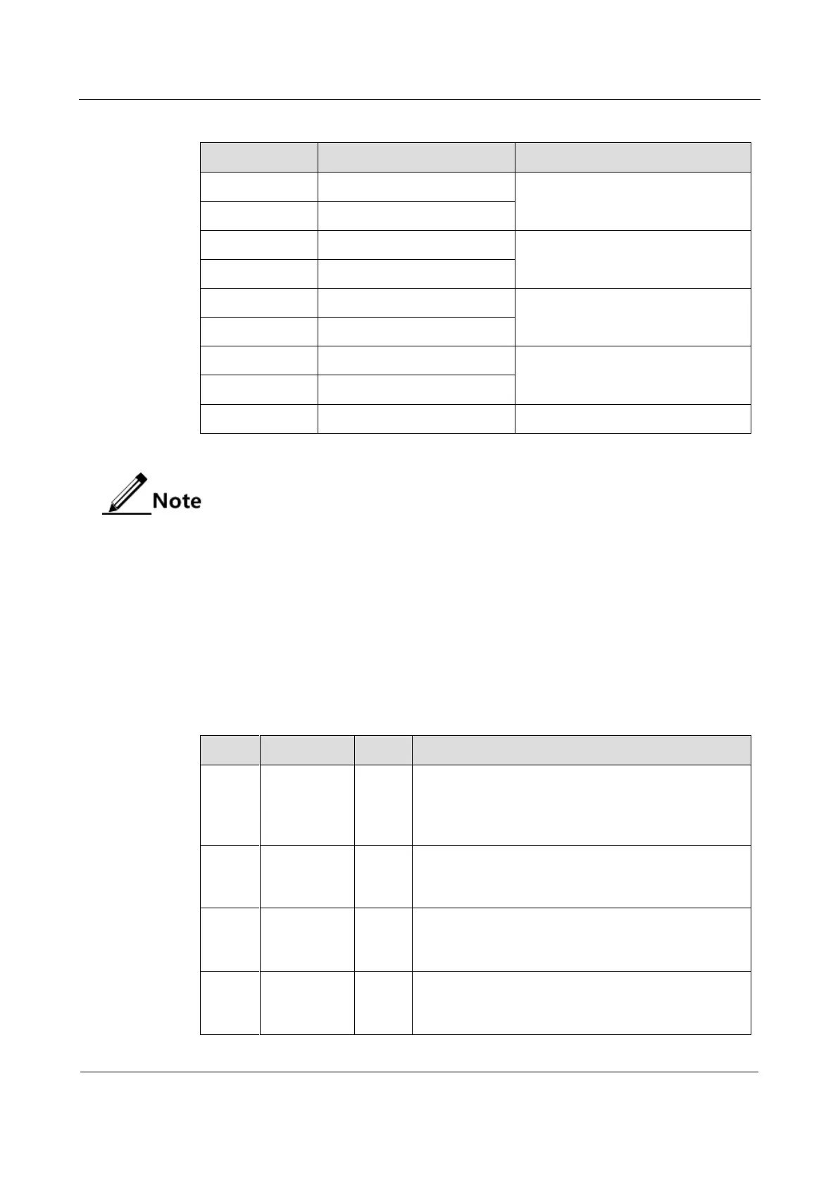
Table 4-1 Definitions of PIN on the DB9 female socket
When the interface impedance is 120 Ω, use the CBL-E1-DB9M/2RJ45-2.5m
cable to connect the RC3000E to the RJ45 head.
When the interface impedance is 75 Ω, use the CBL-E1-DB9M/4BNCF-2.5m
cable to connect the RC3000E to the BNC female interface.
When the interface impedance is 75 Ω, "+" in the table refers to the core of the
coaxial cable. "-" refers to the metallic shield (GND) of the cable.
4.4.4 LEDs
Table 4-2 lists the LEDs on the RC3000E-UP-OPT-FE2E1.
Table 4-2 LEDs on the RC3000E-UP-OPT-FE2E1
System working LED
Blinking green: the system is working properly.
Green: the system is working improperly.
Off: the system is working improperly.
General alarm LED
Red: some alarm is generated.
Off: no alarm is generated.
Local line Loss Of Signal (LOS) alarm LED
Red: some signal on the local line is lost.
Off: no signal on the local line is lost.
Remote line LOS alarm LED
Red: some signal on the remote line is lost.
Off: no signal on the remote line is lost.
 Loading...