3
1.7. Keypad Operation
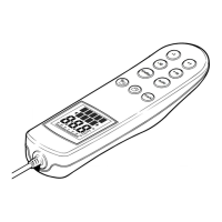
The 10 button key pad is configured in a 4*3 matrix and connected to the
microprocessor P1.0 and P1.6 (pins 2 to 8). Each key is diode isolated to enable
multiple key presses to be decoded.
1.8. Buzzer Operation
TR2 and TR3 are configured as an astable multivibrator with a nominal frequency of
2.7KHz. TR4 is used to switch the buzzer with TR13 acting as an invertor to turn the
buzzer off during a micro-processor reset.
1.9. Illumination Drive
TR10, 12 and 16 provide a constant current drive for lamps LP1, LP2, LP3 and LP4.
The current is set by resistors R56 and R62. TR12 is an inverting buffer to turn off the
lights during a microprocessor reset. Illumination levels are given by pulse width
modulation of drive line P3.3 (pin 15 of lC6).
 Loading...