3
1. Description
The ST7000 course computer is SeaTalk compatible and consists of 2 PCB's, a
course computer and power amplifier. The course computer, which is built using
surface mount technology, contains a microprocessor and various analogue interface
circuitry. The power amplifier provides the motor drive, protection relays and 24V to
12V regulator (24V systems). This PCB is identical to that used on the Autohelm
6000 type 2 pilots (Z051 and Z052) and uses conventional through hole components.
The two PCB's are connected together via a 16 way ribbon cable. The same
computer PCB is used on both 12V and 24V systems. The power amplifier PCB is
built to two standards, one for 12V systems, and a second, which includes a 24V to
12V regulator, for 24V systems. A single design of terminal board is used for all drive
applications. This PCB has no active components and should be visually checked if
suspected faulty. Note:
If the course computer or its PCB are replaced, calibration values previously altered
from the factory settings will require re-setting. Also the Fluxgate Compass will
require re-linearising (auto deviation correction). Both of these procedures are
outlined in the 7000 system section.
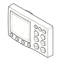
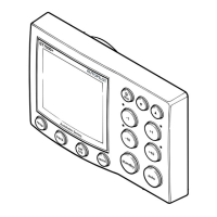
2. Dismantling (reference figures 1 & 2)
1. Unscrew and remove 2 countersunk screws securing lid on terminal box section
and lift off.
2. Unscrew and remove 2 thumb nuts securing extrusion assembly to terminal box
unit and pull extrusion assembly away from terminal box.
3. Course Computer PCB
If servicing course computer PCB, unscrew and remove 4 pan head screws securing
the connector cover moulding to the extrusion and slide out cover and PCB
assembly. Disconnect power amp PCB loom and lift away the PCB assembly. If
necessary, remove the PCB from the moulded cover by unscrewing the 2
countersunk screws and nuts which fix the 'D' connector flange to the moulding.
4. Power Amplifier PCB
Repeat steps 1 to 3 but do not remove the computer PCB from the cover. Disconnect
the 16 way loom from the computer PCB and remove the plastic covers from the
power transistors. Unscrew all pan head screws and retain the shakeproof washers
where fitted. Lift out all transistors. Slide PCB out of extrusion from the open end.
Retain the insulators and caps fitted to the securing lugs on the PCB.
5. If servicing the terminal PCB, repeat steps 1 and 2. Remove the terminal PCB from
the terminal box by removing the 2 nuts securing the 'D' connector to the terminal
box, and the 2 securing screws at the front of the PCB, and remove the PCB
assembly.
 Loading...