4 x Set-up and installation
FA ROTEX HPSU compact (V5) •
23
4.4 Water connection
Ɣ For drinking water lines, comply with the EN 806 and
DIN 1988 stipulations.
Ɣ To avoid a circulation line, install ROTEX HPSU compact
close to the draw-off location. If a circulation line is absolutely
essential, it must be installed in accordance with the
schematics in chapter 9 "Hydraulic system connection".
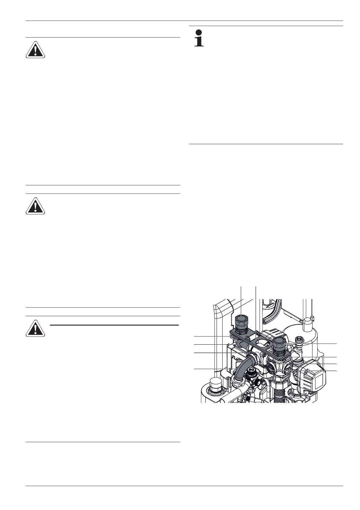
4.4.1 Aligning the connections of the heating feed
and return flow
The connections for the heating feed and return flow can be di-
rected out of the unit upwards or downwards in order to adapt to
the on-site conditions in the most optimum manner.
The unit is delivered with the connections exiting upwards as
standard. In order to direct the connections out from the back of
the unit you must carry out the following conversion steps:
Ɣ Remove the cover hood and the upper thermal insulation
(see chapter 4.3).
Ɣ Pull off both the plug brackets on the connection couplings
(fig. 4-10, item C).
Ɣ Pull
off both connection couplings (fig. 4-10, item B).
CAUTION!
If the ROTEX HPSU compact is con-
nected to a heating system with steel
pipes, radiators or non-diffusion-proof
floor heating pipes, slurry and swarf
could enter the hot water storage tank
and cause blockages, local over-
heating or corrosion.
Ɣ Flush the feed pipes before filling the
heat exchanger.
Ɣ Rinse out the heat distribution
network (in the existing heating
system).
Ɣ Install the dirt filter or sludge
separator into the heating return flow
(see chapter 2.4.5).
CAUTION!
If the ROTEX HPSU compact is con-
nected to a cold water line, where steel
pipes are used, chips can enter the
special steel corrugated pipe heat ex-
changer and remain there. This can lead
to contact corrosion damage and sub-
sequently to leakage.
Ɣ Flush the feed pipes before filling the
heat exchanger.
Ɣ Install contamination filter in the cold
water feed (see chapter 2.4.5).
ONLY ROTEX HPSU COMPACT …BIV
CAUTION!
If the heat exchanger for charging the
pressurised solar system (fig. 4-1 /
fig. 4-2, item 8+9) has an external
heating unit (e.g. wood-burning boiler)
connected to it, an excessive flow tem-
perature at these connections can
damage or destroy the ROTEX HPSU
compact.
Ɣ The feed flow temperature of the
external heater should be limited to
max. 95 °C.
In accordance with EN 12828 you must install a safety
valve at or in the immediate vicinity of the heat
exchanger, with which you can limit the maximum per-
missible operating pressure in the heating system.
T
here should be no hydraulic blocking elements
between the heat generator and the safety valve.
Any steam or heating water which may escape must be
diverted by a suitable blow-off line with constant gradi-
ent in a frost-protected, sa
fe and observable manner.
A diaphragm expansion vessel of adequate dimensions
and pre-set for the heating system must be connected
to the ROTEX HPSU compact. There should be no
hydraulic blocking elements between the heat genera-
tor and the diaphragm expansion vessel.
ROTEX recommends integrating a mechanical
manometer for
the filling of the heating system.
Fig. 4-10 Heating feed and return flow connections aligned upwards
H
C
G
C
B
AB
D
E
F
 Loading...