34
FA ROTEX HPSU compact (V5) •
4 x Set-up and installation
4.5.15 Connection of the ROTEX room thermostat
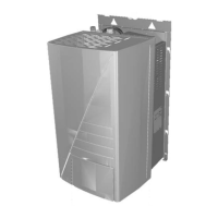
K1/2/3
Relay for backup-heater
L Phase
NNeutral
PE Protective earth conductor
RTX-AL4
Switch board (interface)
RTX-EHS
Switch board (Backup heater)
X1 Terminal block for mains con-
nection to backup heater
X2_1 /2/3
Internal cabling
X3 Plug connection internal ca-
bling to RTX-AL4 circuit
bo
ard
Fig. 4-37 Connections on RTX-EHS circuit board
This component has a separate manual attached,
including among other things instructions for installation
and operation.
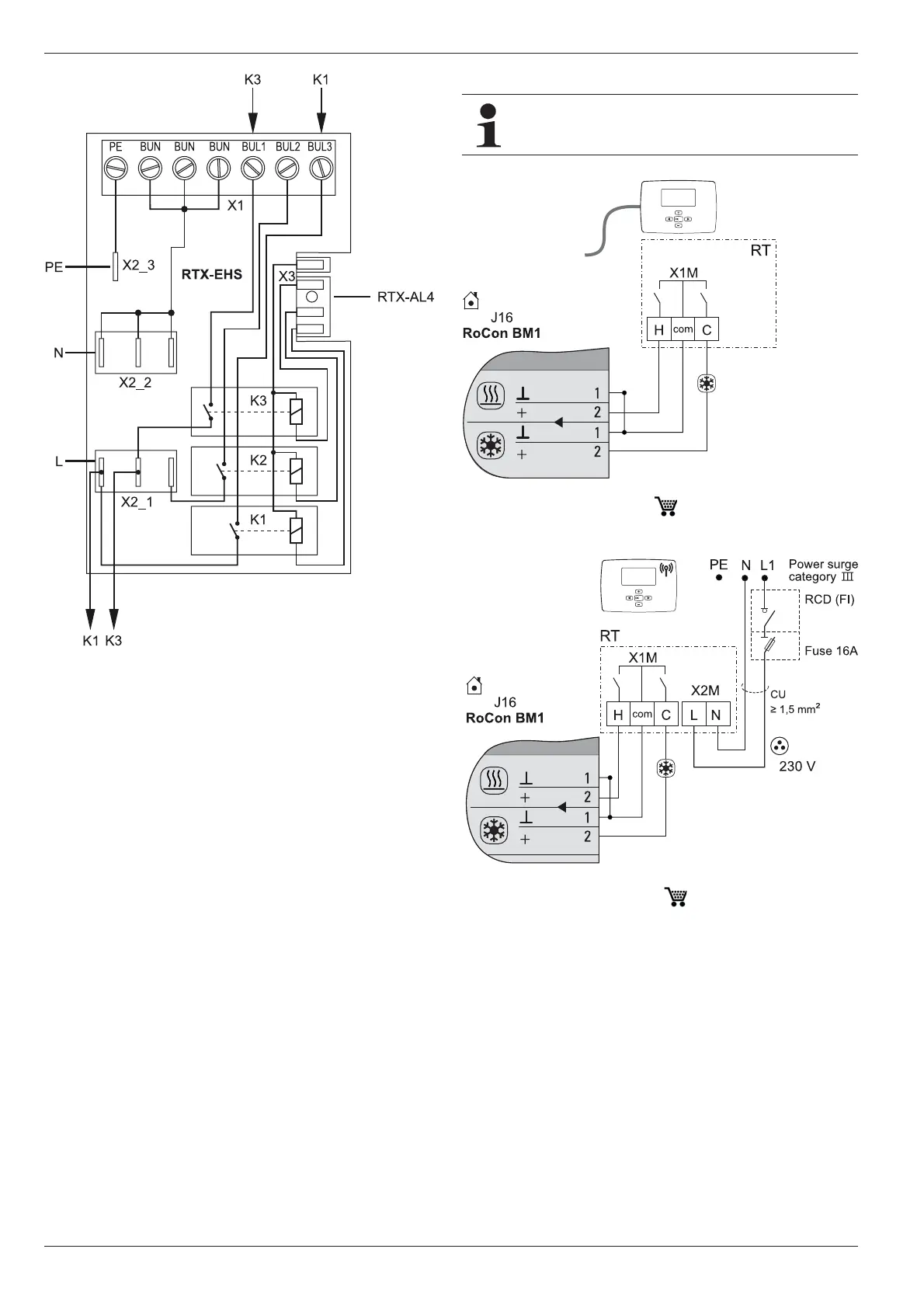
Fig. 4-38 Connection with cabled room thermostat
(RT = ROTEX RKRTW, 14 10 03)
Fig. 4-39 Connection with radio room thermostat
(RT-E = ROTEX RKRTR, 14 10 04)
 Loading...