4 x Set-up and installation
FA ROTEX HPSU compact (V5) •
31
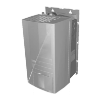
Ɣ Connect the exterior temperature sensor to a twin-core
sensor line (minimum diameter 1 mm
2
).
Ɣ Install the sensor line to the ROTEX HPSU compact.
Ɣ Connect the sensor line to the plug connection J8 on the
board RoCon BM1 (see fig. 4-31).
After connecting the exterior temperature sensor RoCon OT1 to
the regulator RoCon HP of the ROTEX HPSU compact, the pa-
rameter [Outside Config] must be set to "On".
4.5.11 Connection of an external switching contact
By connecting an external switching contact (fig. 4-32) the oper-
ating mode of the ROTEX HPSU compact can be changed.
The current operating mode can be switched thanks to a
changing resistance reading (tab. 4-1). Changing the operating
mode is only effective as long as the external switching contact is
cl
osed.
The operating mode has an effect on the direct circuit of the
ROTEX HPSU compact, and on all other heating circuits that can
be optionally connected to this device.
The operating mode shown in the controller display can deviate
from the operating mode activated in the rotary switch
setting .
An operating mode activated by an external switch contact is
sh
own on the controller by "EXT.", followed by the symbol of the
operating mode (see operating instructions for the controller).
If special functions, such as "Manual Operation" are activated,
the input is not evaluated.
Tab. 4-1 Resistance values for the evaluation of the EXT signal
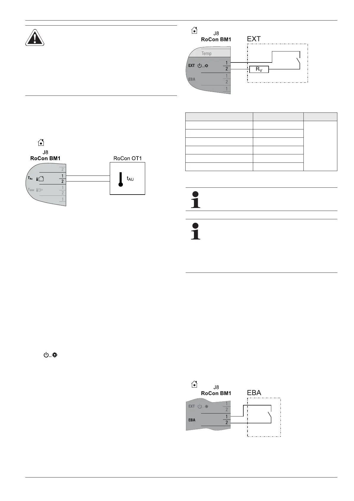
4.5.12 External demand signal (EDS)
By connecting the EDS switch contact to the ROTEX HPSU
compact (fig. 4-33) and through the corresponding parameteri-
sation in its RoCon HP control unit, a heating demand can be
gen
erated via an external switch contact. If the switch contact is
closed, the ROTEX HPSU compact switches to the heating
mode. The flow temperature is adjusted to the temperature that
is set in the parameters [T-Flow Day].
The EDS switching contact has preference
of a request via the
room thermostat.
In Cooling, Stand-by, Manual and Summer mode, the switching
contact is not evaluated. In addition, the heating limits are not
taken into consideration.
CAUTION!
The parallel routing of sensor and mains
lines within an installation pipe can
cause considerable malfunctioning in
the regular operation of the ROTEX
HPSU compact.
Ɣ Always lay the sensor line separately.
Fig. 4-31 Connection of the exterior temperature sensor RoCon OT1 to
the ROTEX HPSU compact (operating as a single solution or
master in a data bus)
Fig. 4-32 Connection of the EXT switching contact
Operating mode Resistance R
V
Tolerance
Standby < 680 ȍ
± 5 %
Heating 1200 ȍ
Reducing 1800 ȍ
Summer 2700 ȍ
Automatic 1 4700 ȍ
Automatic 2 8200 ȍ
When the resistance readings are greater than the
value for "Automatic 2", the input will be ignored.
NOTE REGARDING THE CONNECTION OF A
ROTEX SOLAR SYSTEM
By means of the function [HZ
U] integrated into the
RoCon HP HZU control unit (see operating manual for
the control unit) it is not necessary to connect the EXT
connection with the connection of the burner blocking
contact of the ROTEX solar system.
Fig. 4-33 Connection EBA switch contact
 Loading...